dToF vs iToF: Basic Principles To Real Uses
Table of Contents
dToF vs iToF matters because it enables companies, by objectively weighing the pros and cons of each technology, to select the most suitable technical approach for real-world product development—taking into account specific ranging distances, environmental conditions, accuracy requirements, and cost constraints.
dToF vs iToF: Principles
–dToF Principle: A VCSEL emits pulse signals into the scene. The signals reflect off objects and are received by an SPAD. A TDC records the emission and reception times of the laser pulses. By calculating the time difference and multiplying it by the speed of light, the distance between the object and the sensor can be determined. Square-wave pulse modulation is typically used for the signal because it is relatively easy to implement with digital circuits.
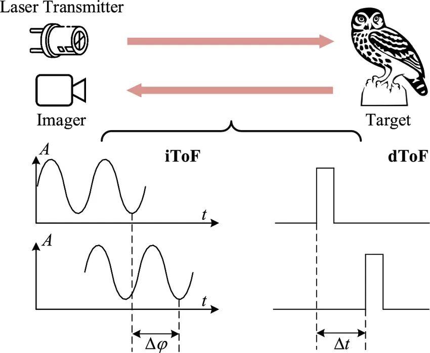
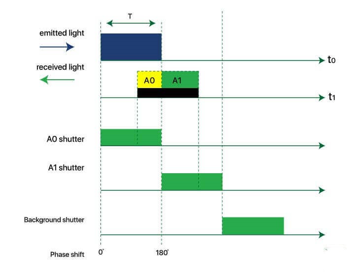
–iToF Principle: A VCSEL emits periodic signals at a specific frequency. The signals reflect off objects and are received by an image sensor. The image sensor calculates the phase difference between the emitted and received signals, indirectly obtaining the time-of-flight of light, and then computes the distance between the object and the sensor.
| dToF | iToF | |
| Principle | Directly measures the time-of-flight of light pulses | Measures the phase difference to indirectly calculate time |
| Distance Formula | d = c × t / 2 | d = c × φ / (4πf) |
Recommended Related Reading from AI Robots Eidos
This article covers the essential differences between dToF and iToF. For a deeper dive into the technical principles, performance benchmarks, and real-world implementation strategies, please read the other two articles that provide a detailed introduction to dToF and iToF.
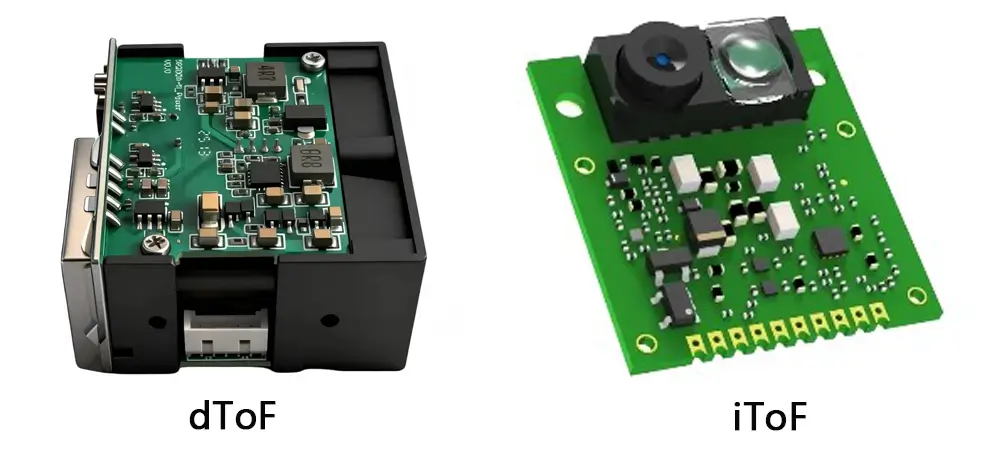
dToF vs iToF: Core Components
| Comparison Dimension | dToF | iToF |
|---|---|---|
| Light Source | VCSEL (pulsed laser) | VCSEL or LED (modulated light) |
| Transmission Optics | Collimating lens / DOE | Diffuser plate |
| Receiver Sensor | SPAD (Single-Photon Avalanche Diode) | CAPD CIS (CMOS Image Sensor) |
| Time Measurement | TDC (Time-to-Digital Converter) | ADC + Phase Demodulation Circuit |
| Signal Processing | Histogram statistics + peak detection | Four-phase sampling + phase demodulation algorithm |
| Output Signal | Direct digital signal | Analog signal → ADC → digital processing |
| Pixel Process | SPAD (complex process, larger pixel size) | CMOS CAPD (mature process, smaller pixel size) |
dToF vs iToF: Performance
| Dimension | dToF (Direct) | Pulsed iToF | CW iToF (Phase) |
| Accuracy | ★★★★★ | ★★★ | ★★★★ |
| Long-range Performance | Excellent | Fair | Fair |
| Resolution | Medium | Medium | Relatively High (VGA-level) |
| Power Consumption | Relatively High | Medium | Relatively Low |
| Cost | Relatively High | Medium | Relatively Low |
| CMOS Compatibility | Challenging | Medium | Very Good |
| Multi-target Interference Rejection | Strong | Fair | Fair |
| Maturity | Rapidly Developing | Less Commonly Used | Most Mature |
| Representative Products | iPhone LiDAR | Industrial Sensors | Kinect, Android Phone TOF |
dToF vs iToF: Advantages and Disadvantages
| Type | Advantages | Disadvantages |
| dToF | High accuracy: Since it directly measures the time-of-flight, dToF offers high ranging accuracy, making it suitable for scenarios requiring high-precision measurements. | Higher hardware requirements: requires high-precision clocks for measurement; needs to generate high-frequency, short-duration, high-intensity pulsed optical signals. |
| Long-range measurement: dToF can measure at relatively long distances, making it suitable for applications requiring long-range distance sensing. | The optical pulse signals detected by dToF are typically at the nanosecond or picosecond level, so SPADs need to achieve high precision. | |
| Strong anti-interference capability: dToF is relatively insensitive to ambient light interference and can maintain stable measurement performance in complex environments. | Compared to CMOS image sensors, SPADs generally have lower integration levels, resulting in relatively poor resolution and higher cost. | |
| dToF depth algorithms are relatively simple. | ||
| iToF | Suitable for short-range distance measurement. | Lower accuracy: detection range is relatively short, and accuracy degrades as distance increases. |
| Since iToF sensor pixels are relatively small, they can achieve relatively high image resolution. | High power consumption: power consumption increases with distance. | |
| Low cost. | Susceptible to ambient light interference. | |
| Depth algorithms are relatively complex. |
dToF vs iToF: Applications
–dToF:
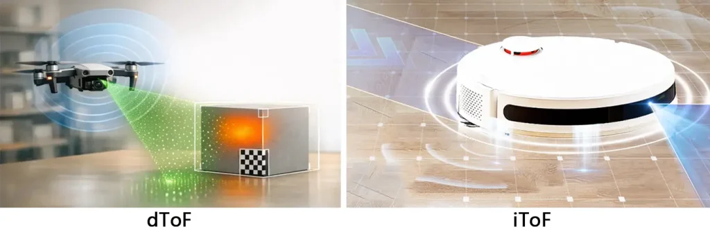
dToF features low power consumption and a compact size, making it more suitable for applications such as industrial robots that require fast ranging and obstacle detection, as well as other space-constrained compact designs.
dToF demonstrates good resistance to environmental interference. Currently, its ranging accuracy in outdoor scenarios is higher than that of iToF, giving it an advantage in outdoor application scenarios.
–iToF
iToF offers higher image resolution, enabling it to reproduce more detailed scene information in application scenarios such as object recognition, 3-Dimensional reconstruction, and behavior analysis. It holds advantages in fields like robotics and new retail.
| Application | Distance | Recommended Solution | Reason |
| Robot Vacuum Obstacle Avoidance | <5m | iToF | Low cost, high resolution, good frame rate |
| Smartphone | <1m | dToF | Strong ambient light resistance, low power consumption |
| Automotive LiDAR | >100m | dToF | Long range, strong ambient light resistance |
| Drone Obstacle Avoidance | <20m | dToF | Strong ambient light resistance, long range |
| Proximity Sensing | <0.5m | iToF | Low cost |
dToF vs iToF: Technological Breakthroughs
iToF
–Pixel Process and Resolution Enhancement: Since 2018, iToF pixel sizes have continued to shrink, from the early 10μm level down to the current 3.5μm level; resolution has progressively advanced from QVGA towards VGA and megapixel levels. In 2020, Sony launched a 3-dimensional stacked back-illuminated structure iToF sensor with a resolution of 1290×960. In 2024, MIT research achieved an iToF pixel structure with a resolution of 1290×1080.
–Accuracy and Modulation Frequency Upgrades: By increasing modulation frequencies and employing multi-frequency fusion algorithms, short-range ranging accuracy has improved from centimeter-level to millimeter-level.
–Power Consumption and Integration Optimization: Pixel-level integration processes continue to mature, chip area continues to shrink, and combined with dynamic power regulation technology, they adapt to the low-power requirements of mobile devices.
dToF
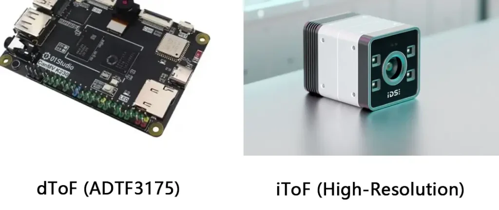
–Significant Resolution Leap: Early dToF focused on single-point or low-resolution arrays. For example, ST’s first-generation product only offered single-point ranging, and ams OSRAM’s previous-generation product had an 8×8 array. In 2025, ams OSRAM released the TMF8829, increasing resolution from 64 points to 1536 points (48×32)—a nearly 24-fold increase in sampling points—significantly improving spatial modeling and object recognition accuracy. ADI’s ADTF3175 achieves 1024×1024 (1 megapixel) area-array dToF imaging with depth accuracy of ±5mm, capable of capturing subtle object shapes and motion trajectories.
–SPAD Process and TDC Accuracy Upgrades: Single-photon detection efficiency continues to improve, and the time resolution of Time-to-Digital Converters (TDCs) has entered the picosecond level, supporting longer-range ranging and higher accuracy.
–Stratified Product Portfolio Enhancement: Two main product series have emerged—single-zone high-precision ranging and multi-zone spatial perception—covering ranging needs from 1cm to 5 meters, suitable for differentiated scenarios such as smartphone autofocus, gesture recognition, and spatial modeling.
dToF vs iToF: Respective Technology Development Directions
–dToF:
| Direction | Description |
| SPAD Pixel Miniaturization | Improve spatial resolution |
| 3-Dimensional Stacking Process | Vertical stacking of SPAD + TDC + logic circuits |
| All-Solid-State LiDAR | Flash / OPA scanning |
| 1550nm Wavelength | Longer detection range |
–iToF
| Direction | Description |
| Higher Modulation Frequency | Improve accuracy |
| Multi-Frequency Fusion Algorithm | Mitigate multipath interference |
| Pixel-Level Integration | Higher resolution (1MP+) |
| Low-Power Design | Optimize battery life for mobile devices |
dToF vs iToF: Technology Fusion
dToF and iToF technologies each have their own strengths and weaknesses. dToF offers stable long-range measurement and strong anti-interference capability, but has lower resolution and complex circuitry that is difficult to integrate. iToF offers high resolution and ease of integration, but its measurement range is limited and its anti-interference capability is weak. Hybrid ToF systems can combine the advantages of both and compensate for their respective shortcomings.
–Hardware Fusion: dToF pixels (SPADs) and iToF pixels (CMOS CAPDs) are interleaved or mixed on the same sensor chip, enabling simultaneous acquisition of both types of data on a single chip. For example, dToF pixels provide long-range absolute distance and anti-interference capability, while iToF pixels provide dense depth and texture information at close range—the two complement each other to generate a more complete depth map.
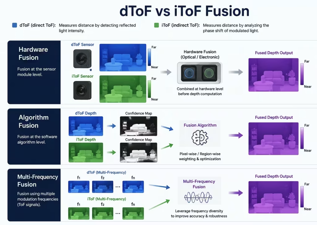
–Algorithm Fusion: In the same optical system, time-division or zone-division methods are used to perform ranging with iToF and dToF separately, and then the data is fused through algorithms. For instance, dToF is used to provide long-range “depth anchors” to eliminate iToF’s “distance ambiguity,” while iToF’s high resolution is used to densify and complete the sparse point cloud from dToF.
–Multi-Frequency Fusion: Combining both technologies can further enhance ranging robustness in complex scenarios (such as specular reflections and concave corners).
In recent years, some hybrid ToF products have also emerged.
Infineon’s REAL3 flexible ToF imager technology integrates existing high-resolution iToF flood illumination and dToF long-range point-source illumination into a single hybrid ToF camera. By adding precise long-range spot data, it creates an accurate 3D map of the surrounding area.
Toppan’s hybrid ToF achieves distance measurement of up to 30 meters. Toppan’s hybrid ToF focuses on enhancing system robustness. Compared to traditional iToF systems, its hybrid system increases sensing distance, especially in outdoor applications.
Insight from AI Robots Eidos about dToF vs iToF
The key in the future may no longer be which has higher resolution, dToF or iToF, but rather how the resolution improvements of both will unlock new application scenarios. The high-resolution, long-distance imaging of dToF is expected to challenge structured light technology in fields such as facial recognition.
dToF has higher distance measurement accuracy in outdoor scenarios compared to iToF. With the explosive growth of applications like outdoor robotics, drone delivery, and smart traffic, the anti-interference capability of dToF will become a core competitive advantage that is hard to replace. If iToF wants to make an impact in outdoor settings, it must achieve breakthroughs in anti-interference algorithms and hardware design; otherwise, dToF will maintain a lasting advantage over iToF.
The 3-Dimensional ISP engine is crucial for eliminating interference, reducing power consumption, and enhancing real-time performance. This means that, regardless of whether it is dToF or iToF, the ultimate performance ceiling may not depend on the sensor itself but rather on back-end signal processing capabilities. Whichever technology can achieve breakthroughs in 3-Dimensional ISP first will gain a significant experiential advantage under comparable hardware conditions.
Image Credits: Researchgate & Erdicn & Wiseomeinc & AI & Maxictech & Piecarte & Electronics-lab & Automate