
Table of Contents
Gantry robots, built on a Cartesian coordinate system, feature ultra-long stroke, high rigidity, and high load capacity, filling application scenarios that articulated robots cannot cover—such as heavy-load material handling in the manufacturing sector.
What Is A Gantry Robot?
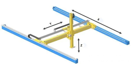
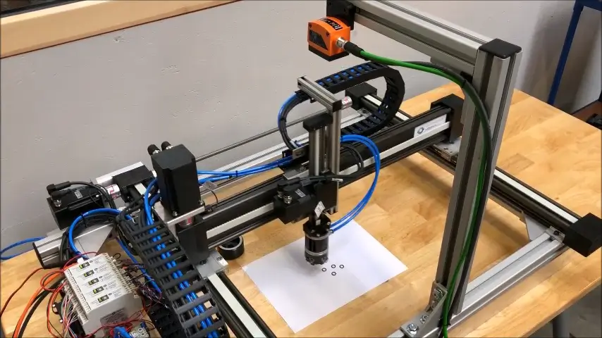
A gantry robot is a fully automatic industrial robot based on a Cartesian X, Y, Z three-axis coordinate system. It adjusts the position of objects or enables trajectory movement of workpieces.
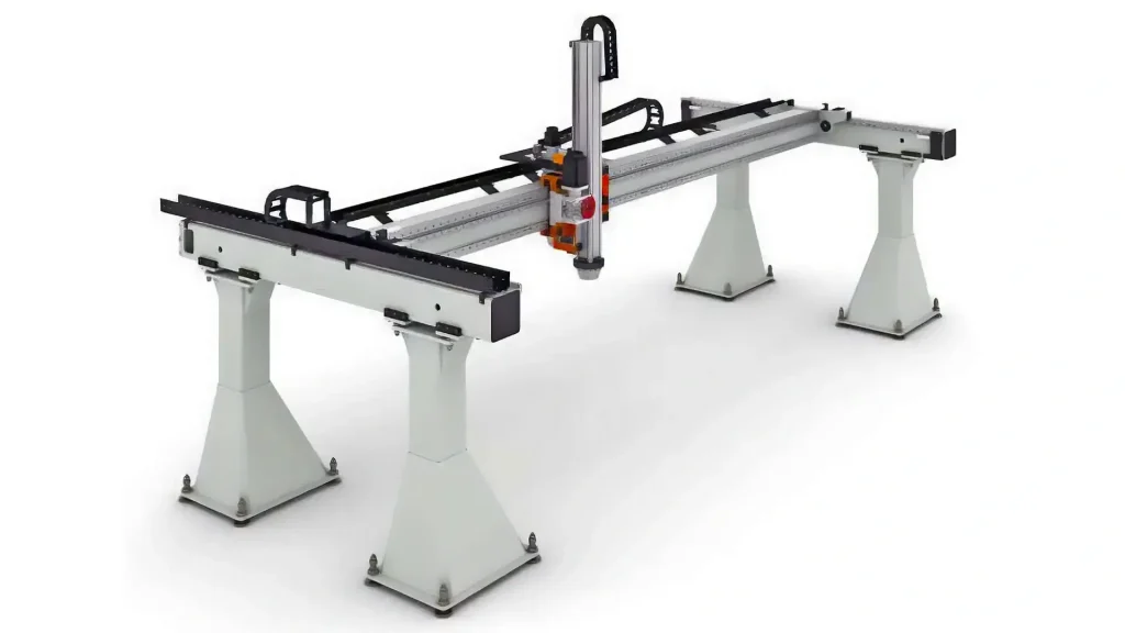
The core of a gantry robot is realized through an industrial controller (e.g., PLC). The controller analyzes and processes input signals from various sensors, buttons, etc., makes logical decisions, and issues execution commands to output components (relays, motor drivers, indicator lights, etc.). This achieves coordinated motion among the X, Y, and Z axes, completing a full set of automated workflows.
Structure of a Gantry Robot System
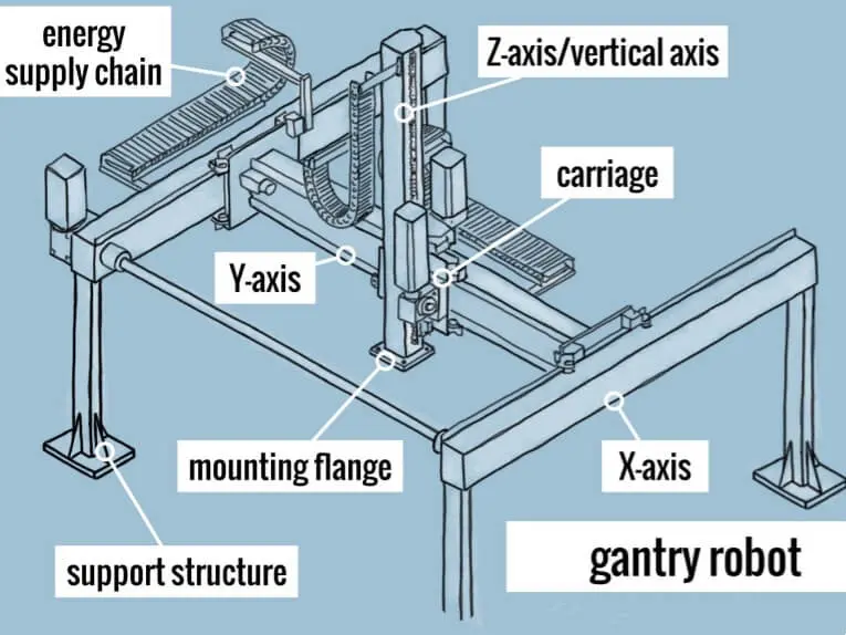
A gantry robot system mainly consists of five modules: a rigid frame, linear transmission mechanisms, a servo drive system, an end effector, and a control system. Unlike the flexible design of articulated robots (e.g., collaborative robots or six-axis robots), the structure of gantry robots is centered around the core requirements of long stroke, high rigidity, stable handling, and low deformation.
–Main Frame: Constructed from high-strength carbon steel trusses or aviation-grade aluminum alloy profiles. Structural mechanics are optimized via finite element simulation, eliminating redundant structures while maximizing overall rigidity. The integrated frame effectively avoids beam vibration and deflection issues during long-stroke motion. For heavy-load scenarios, mainstream solutions adopt dual-column support and dual-drive synchronous structures, combined with thickened beam designs, to ensure structural stability under ultra-long strokes of up to 30 meters and high-speed reciprocating motion.
–Transmission System: Designed for high-speed light-load and low-speed heavy-load applications.
Light-load, high-speed scenarios (e.g., photovoltaic glass): Linear motor direct-drive solutions are used, with positioning resolution reaching sub-micron levels and maximum handling speeds up to 2 m/s, suitable for high-frequency pick-and-place operations on assembly lines.
Heavy-load scenarios (e.g., thick steel plates): High-precision rack-and-pinion drives with dual-motor synchronous anti-backlash structures are employed, paired with heavy-duty linear guides to effectively cancel transmission backlash and ensure positioning stability under heavy loads, with no long-term precision drift.
High-end models have adopted third-order or fourth-order S-curve trajectory planning algorithms. By smoothing the jerk (rate of acceleration change), these algorithms solve the acceleration discontinuity problem of traditional trapezoidal velocity profiles, significantly reducing inertial shocks during high-speed start/stop operations—primarily used for precision material handling.
–Control System: The three-axis motion of a gantry robot is fully decoupled, enabling simpler and more efficient control algorithms with faster response. Mainstream high-end models are equipped with EtherCAT high-speed bus control systems, supporting millisecond-level signal responses. They can interface with stamping, cutting, grinding, and warehousing equipment. By integrating TSP (Traveling Salesman Problem) time-optimal path planning, they reduce idle-stroke losses and improve overall line efficiency.
Advantages and Disadvantages of Gantry Robots
Advantages
Gantry robots adopt a gantry frame + three-axis orthogonal linear motion structure. Their working envelope is a regular rectangular space, and the motion axes are fully decoupled, making them inherently suitable for long-span, large-area, planar sheet-material production scenarios. The X-axis can be modularly extended beyond 30 meters; for strokes exceeding 30 meters, sectional dual-drive synchronous systems and reinforced factory foundations are required.
Load capacity covers a full range from 5 kg to 20 tons. Medium-load production lines typically deploy 1–5 ton gantry robots, which reliably meet the handling needs of various materials (e.g., plates, profiles).
Disadvantages
The disadvantages of gantry robots are equally evident. They require larger floor space and impose higher demands on factory floor flatness and foundation load-bearing capacity. In applications involving short workstations, confined spaces, or multi-angle workpiece tilting, the overall flexibility of gantry robots is inferior to that of six-axis robots.
| Parameter | Gantry Robot | Six‑Axis Robot |
| Working Range | 20 m × 10 m × 3 m | Φ3 m spherical workspace |
| Load Capacity | ≤ 2000 kg | ≤ 500 kg |
| Trajectory Accuracy | ±0.1 mm | ±0.05 mm |
Cartesian Robots vs. Gantry Robots
These two terms often overlap in industrial automation. Simply put, Cartesian robots are the broader category, and gantry robots are a subcategory—a type of Cartesian robot. This is why gantry robots are also known as Cartesian gantry robots.
The structural feature of a gantry robot resembles a “door.” It typically consists of two parallel rails supporting a beam (X-axis), with a carriage moving along the beam (Y-axis) and a vertical axis (Z-axis) suspended underneath. The space below is completely open. This structure is highly suitable for large-span, heavy-load applications, such as handling large automotive components.
| Name | Core Distinction | Metaphor |
|---|---|---|
| Cartesian Robot | General term for a technical definition | Mathematical model |
| Gantry Robot | Dual‑side support, large span, and high load capacity | Large gantry crane |
Recommended Related Reading from AI Robots Eidos
Cartesian robot is a very important type of industrial robot, so AI Robots Eidos also provides a detailed introduction to this type of robot. Interested readers can read this article.
Cartesian Robots: What You Need to Know
Technical Parameters of Gantry Robots (For Reference Only)
| Item | X‑axis | Y‑axis | Z‑axis |
| Dimension | ≤50 m | ≤15 m | ≤3 m |
| Load | 10 t | ||
| Speed | 1000 mm/s | 1000 mm/s | 800 mm/s |
| Acceleration time | 2 s | 2 s | 2 s |
| Guide | Linear rail | Linear rail | Linear rail |
| Transmission | Gear / rack | Gear / rack | Gear / rack |
| Drive | Servo motor | Servo motor | Servo motor |
| Structure | Overhead rail with gear‑rack meshing | Overhead rail with gear‑rack meshing | Fixed arm / Telescopic arm |
Interpretation of Gantry Robot Technical Parameters
For the convenience of readers, this section builds on the previous chapter.
| Category | X‑axis | Y‑axis | Z‑axis | Analysis and Significance |
| Stroke | ≤50 m (customizable) | ≤15 m | ≤3 m | X‑axis stroke up to 50 m, capable of covering ultra‑long production lines or cross‑workshop operations; 15 m stroke on Y‑axis satisfies large‑area multi‑station scheduling; 3 m lifting stroke on Z‑axis suits deep‑station pick‑up or high‑level palletising needs. |
| Load | 10 t | 10 t | 10 t | The 10‑ton ultra‑high load capacity is designed for heavy‑duty industrial scenarios, capable of handling large construction machinery components, heavy metal billets, and similar materials. |
| Speed | 1000 mm/s | 1000 mm/s | 800 mm/s | X/Y axes run at 1 m/s high speed, ensuring cycle times for long‑distance handling; Z‑axis lifting speed of 0.8 m/s maintains efficiency under heavy loads while keeping workpiece posture stable. |
| Acceleration time | 2 s | 2 s | 2 s | Designed for 10‑ton heavy loads, the 2‑second acceleration time prioritises system stability, avoids inertial shock damage to mechanical structures and heavy workpieces, and extends equipment life. |
| Guide | Linear rail | Linear rail | Linear rail | High‑rigidity linear guides ensure motion straightness and parallelism, providing a foundation for precise positioning under heavy loads; optional V‑rails and other types are available. |
| Transmission | Rack and pinion | Rack and pinion | Rack and pinion | Rack‑and‑pinion transmission has no accumulated error and offers high rigidity; it is the preferred choice for long‑stroke, heavy‑load applications, efficiently transmitting torque. |
| Drive | Servo motor | Servo motor | Servo motor | Enables highly synchronised multi‑axis motion, ensuring accurate posture of heavy workpieces. |
| Structure | Overhead rail with gear‑rack meshing | Overhead rail with gear‑rack meshing | Fixed arm + telescopic arm | Strong lateral force resistance, smooth lifting, especially suitable for eccentric loads or oversized objects. |
Key Technical Points for Gantry Robot Selection
–Load Curve Analysis:
Dynamic load is the core basis for robot selection and trajectory planning. Both static load and dynamic inertial forces must be considered comprehensively.
Typical formula: F_total = m × (a + g) + F_friction
m × g = static load; m × a = dynamic load; F_friction = friction load
–Rigidity Calculations:
Deflection Calculation: Mid-span deflection should be ≤ L/1500 (L = span). For example, for a span of 4.5 meters, allowable deflection is ≤ 3 mm (4500/1500 = 3) to ensure positioning accuracy over long strokes.
Inertia Ratio Calculation: Inertia ratio = load inertia (JL) / motor rotor inertia (JM). This ratio directly affects system stability. Traditional experience recommends controlling it within 10:1, but modern servo systems can support higher ratios (e.g., 50:1).
–Control System Selection:
Control System: Mainstream configuration uses PLC; high-end/complex scenarios use PAC.
Motion Control: Supports spline interpolation and look-ahead algorithms.
Communication: Synchronous buses (e.g., EtherCAT) eliminate synchronization errors; interfaces like PROFINET and Modbus ensure real-time connectivity with PLCs and MES systems.
Safety Functions: Performance Level (PL) – industrial gantry robots typically require PL d (note: PL levels are a, b, c, d, e; higher levels mean better safety performance). Ingress protection (IP) ratings are determined by the operating environment and must meet corresponding levels (e.g., IP54, IP67) to ensure safety.
Gantry Robot Market Analysis
Competitive Strategies
Competition in the gantry robot industry is intense. Companies adopt differentiated strategies based on their capabilities, market positioning, and core strengths.
–Providing Customization Services
High-Speed Gantry Robot Customization: Maximum load capacity up to 600 kg, with full-load running speeds up to 3.6 m/s. Helps enterprises achieve lean production and cost reduction in key links such as transfer and storage, meeting personalized needs of high-load, high-throughput industries (e.g., tire manufacturing).
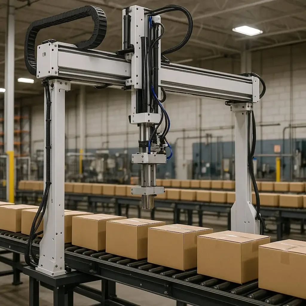
Heavy-Duty High-Precision Gantry Robot Customization: Equipped with barcode positioning, achieving positioning accuracy up to 1 mm; max load capacity 2,000 kg; light-load max speed up to 3 m/s. Provides stable and efficient intelligent operations for industries requiring high precision—new energy, auto parts, 3C manufacturing, mechanical manufacturing—helping optimize production processes.
–Building Technological Barriers
Leading companies establish barriers by using precision transmission components, advanced servo control algorithms, and structural optimization for long strokes. For example, top-tier manufacturers use integrated precision cast-aluminum frames, self-developed linear motor drive systems, combined with mature fourth-order trajectory control and high/low-order coupled servo technologies. This ensures high precision stability and long service life under ultra-long strokes (over 10 meters) and high-speed precision handling.
–Serving Specific Customers
Deeply cultivating specific verticals and providing highly customized solutions for particular scenarios. For instance, using long-stroke dynamic error compensation algorithms to maintain dynamic positioning accuracy without significant degradation over 30-meter strokes, primarily serving high-value-added industries such as semiconductors, precision optics, and aerospace.
Development Challenges
–Technology: Extreme industrial environments pose extreme challenges to rigidity, stability, and dynamic accuracy. For example, maintaining micron-level repeatability over a 30-meter span while carrying tens of tons and running at high speeds involves complex structural mechanics and thermal deformation compensation—high technological barriers.
–Talent: Designing, integrating, and commissioning gantry robot solutions requires cross-disciplinary talent in mechanical, electrical, software, and process engineering. Some manufacturers excel only in mechanical structures but lag in intelligent control and data algorithms, slowing product intelligence upgrades.
–Ecosystem: Excellent solutions require deep synergy between the robot body, end tools, sensing systems, and upper-level MES/ERP providers. Due to high investment needs, many companies can only supply machinery, lacking ecosystem integration capabilities and failing to deliver truly efficient solutions.
Gantry Robot Applications
–Electronics Industry: Equipped with a vision positioning system (CCD resolution 1280×1024), it can inspect mobile phone glass covers (1,200 pieces/hour). With flexible grippers on the end effector (contact force adjustable 0.1–5 N), it can insert circuit boards (positioning accuracy ±0.02 mm).
–Automotive Industry:
Welding: Completes 300 weld points per hour within a 6m × 4m working range.
Press line loading/unloading: Works with a 2,000T press to handle sheet materials at a rate of 12 times per minute.
–Mechanical Industry: Equipped with a six-axis force-controlled grinding head, it deburrs castings. With laser ranging for real-time compensation, it bends sheet metal parts. It can also handle large components such as wind turbine hubs.
Insight from AI Robots Eidos about Gantry Robots
Future ultra‑long‑stroke gantry robots should not be viewed merely as standalone “handling devices,” but rather as the physical end‑actuators of a “shop‑floor‑level operating system.” With an X‑axis coverage of up to 50 meters, the gantry robot becomes the “global coordinate origin” of the entire production workshop. By integrating real‑time edge computing, it no longer passively executes PLC instructions; instead, it dynamically adjusts its motion trajectories and cycle times in response to upstream production‑schedule changes and downstream equipment status. For example, when it detects a delay in one machine tool’s processing, the robot can autonomously plan a “detour path” to first serve other workstations, thereby achieving dynamic real‑time scheduling at a macroscopic scale.
Future high‑end gantry robots will incorporate distributed fiber‑optic temperature sensors to monitor in real time the temperature rises of guide rails, racks, and the ambient environment. Through machine‑learning modelling, they will accurately predict beam deflection and thermal elongation under varying ambient temperatures and operational loads. This is no longer a simple compensation algorithm, but a “self‑aware” machine body—generating, during operation, a virtual motion command of “reverse deformation” in real time to counteract physical distortion.
Future gantry robots will move towards a structure composed of standardised joint modules and reconfigurable truss frameworks. Enterprises will no longer need to purchase a complete machine with a specific span; instead, they will procure standardised high‑strength aluminium‑alloy joint profiles, linear‑motor modules, and intelligent locking mechanisms. When products are renewed or production lines are reconfigured, operators can, like assembling “industrial Lego,” complete the re‑assembly and span adjustments within days. Accompanying this will be the emergence of “motion‑control application stores,” which automatically download the corresponding dynamic parameters and safety logic based on different combinations, transforming equipment from a capital expenditure (CAPEX) item into a flexibly configurable operational resource (OPEX), thus significantly reducing long‑term investment risks.
Image Credits: Fuyumotion & Mwes & Web & Ccmrails & Rbtx