iToF: A Complete Technical Overview
Table of Contents
iToF (Indirect Time-of-Flight) is a depth-sensing technology that indirectly calculates the time of flight by measuring the phase difference between the emitted light and the reflected light, thereby computing the distance.
Principle of iToF
iToF (Indirect Time-of-Flight) is a 3-Dimensional depth imaging technology. Its core principle is that, instead of directly measuring the round-trip time of light pulses, it indirectly calculates the time of flight by measuring the phase difference between the emitted and reflected light, and then computes the distance.
The imaging model of iToF can be simplified as:
M = I + A · cos(φ + θ)
where
M is the pixel measurement value, I is the ambient light intensity coefficient, A is the scene reflectance coefficient, φ is the phase difference caused by light flight, and θ is the modulation parameter (frequency and phase). To solve for φ (and thus obtain depth), at least three measurements with different θ values are required to jointly solve for the three unknowns I, A, and φ.
Classification of iToF
Continuous-Wave Modulation (CW-iToF)
Continuous-wave modulation uses a sustained, continuously varying waveform (e.g., sine wave) for modulation. By periodically modulating the continuous output of the light source, a modulated signal at a specific frequency is generated. When the modulated light signal hits an object and returns to the sensor, the sensor analyzes the phase difference of the received signal to calculate the flight time of the light signal. Continuous-wave modulation allows for the selection of different modulation frequencies to optimize measurement accuracy and range for different application scenarios.
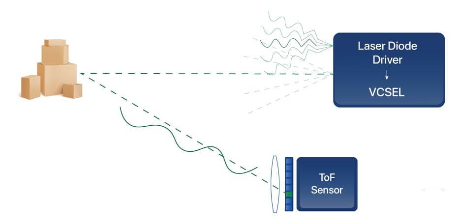
It can be further subdivided by demodulation method.
| Subtype | Principle | Characteristics |
| 2-tap | Demodulates using 2 sampling points | Simple structure, low cost, but limited accuracy |
| 3-tap | Demodulates using 3 sampling points | Higher accuracy can eliminate some errors |
| 4-tap | Demodulates using 4 sampling points (0°, 90°, 180°, 270°) | Highest accuracy, mainstream solution |
Pulse Modulation (Pulsed-iToF)
Pulse-modulated indirect Time-of-Flight technology relies on the light source emitting optical signals in short pulses. These light signals reflect back to the receiving sensor after hitting an object. By measuring the time from emission to reception of the light pulses and combining this with the speed of light, the distance between the object and the sensor can be accurately calculated. In indirect ToF systems, light pulses are typically not used to directly measure their round-trip time; instead, distance information is derived through modulation and demodulation methods.
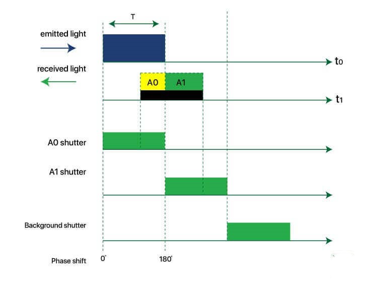
| Dimension | CW-iTOF (Continuous Wave) | P-iTOF (Pulse Wave) |
| Sampling Method | Four-phase sampling (0°/90°/180°/270°) | Dual sampling + background light compensation (0°/180°/BG) |
| Power Consumption | Relatively high (continuously emits modulated light) | Lower (pulses emitted intermittently) |
| Ambient Light Immunity | Fair | Stronger (background light compensation mechanism) |
| Frame Rate | Fair | Higher (high signal duty cycle) |
| Accuracy | High | High |
| Motion Blur | More noticeable (4 sub-frames compose 1 frame) | Shorter exposure time, less motion blur |
Key Components of iToF
–VCSEL (Vertical-Cavity Surface-Emitting Laser): Compared to EEL (Edge-Emitting Laser), its advantages include: circular symmetric beam spot for easy beam shaping, low-cost array packaging, small wavelength drift with temperature, and suitability for high-speed modulation (>100 MHz). Multi-junction VCSELs can increase single-pixel power without increasing area, making them a key process technology for current consumer-grade iToF.
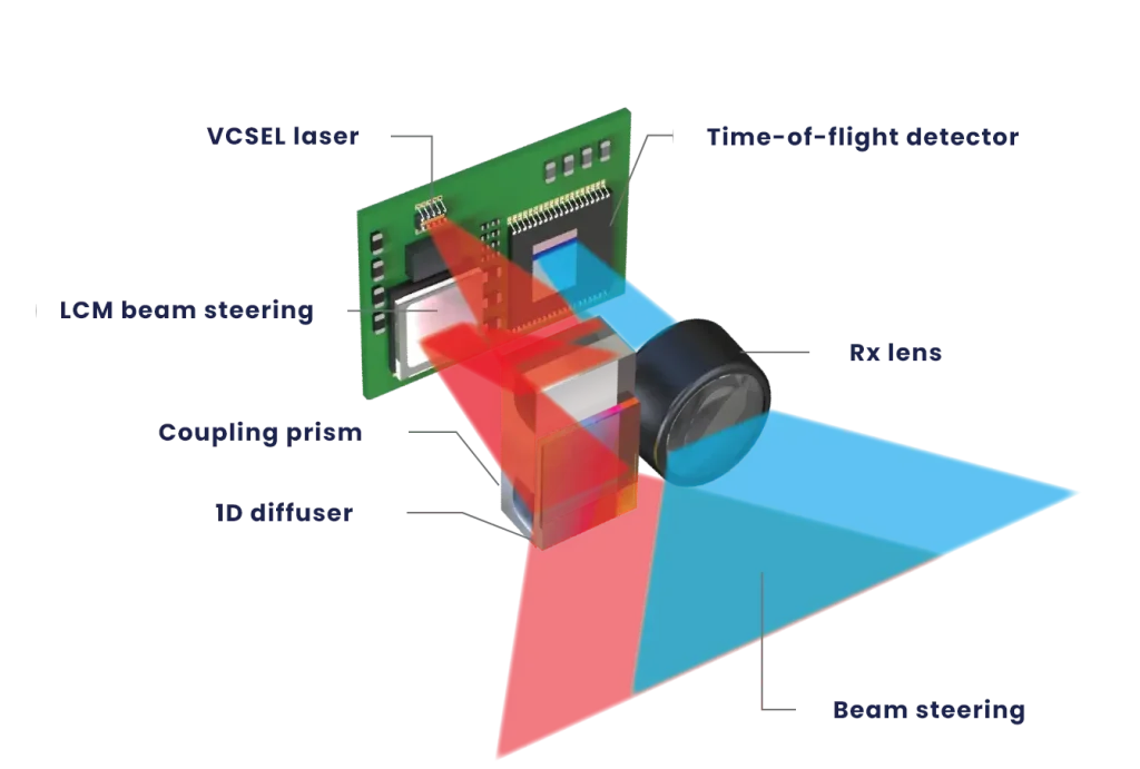
–Modulation Driver: It is responsible for injecting sinusoidal/square wave currents into the VCSEL. The driver bandwidth directly determines the achievable fm, which in turn sets the upper limit of accuracy. The driver’s power consumption often accounts for 30%–50% of the entire module, making it a key focus for thermal management and battery life design.
–Diffuser: The diffuser shapes the point light source into a flood illumination that covers the entire field of view (FoV). iToF typically uses flood illumination for ranging rather than point-by-point scanning, which is the fundamental reason for its lower cost compared to mechanical/MEMS-based dToF.
Recommended Related Reading from AI Robots Eidos
If iToF is the “reliable faction” in the field of depth perception, finding a perfect balance between distance and cost through sophisticated phase calculations at close ranges, then dToF (direct time of flight) is more like a “hardcore powerhouse” — it directly emits short light pulses and precisely measures their round-trip time to measure distances more directly. Due to this fundamental difference in principles, dToF demonstrates unique advantages in long-distance and complex lighting environments.
Interested readers can check out this article introducing dToF.
–ADC Circuit: The four-phase integrated values output by the pixels are quantized by a high-speed ADC (typically 10–14 bits) and then sent to an on-chip or external depth engine for phase inversion, unwrapping, and multi-frame fusion to output a depth map.
Advantages of iToF
–Resolution: The technology is relatively mature, with high image resolution. Most image resolutions are 320×240 pixels, and Microsoft’s latest Kinect offers multiple resolutions up to 1024×1024 pixels. In application scenarios such as object recognition and behavior analysis, it can reproduce more detailed scene information, giving it an advantage in robotics, new retail, and other application fields.
–System Integration: In terms of system integration, iToF is easy to integrate and does not require additional measurement circuitry. Moreover, it has a compact form factor and can be easily integrated into space-constrained terminal devices such as smartphones, tablets, and smart displays.
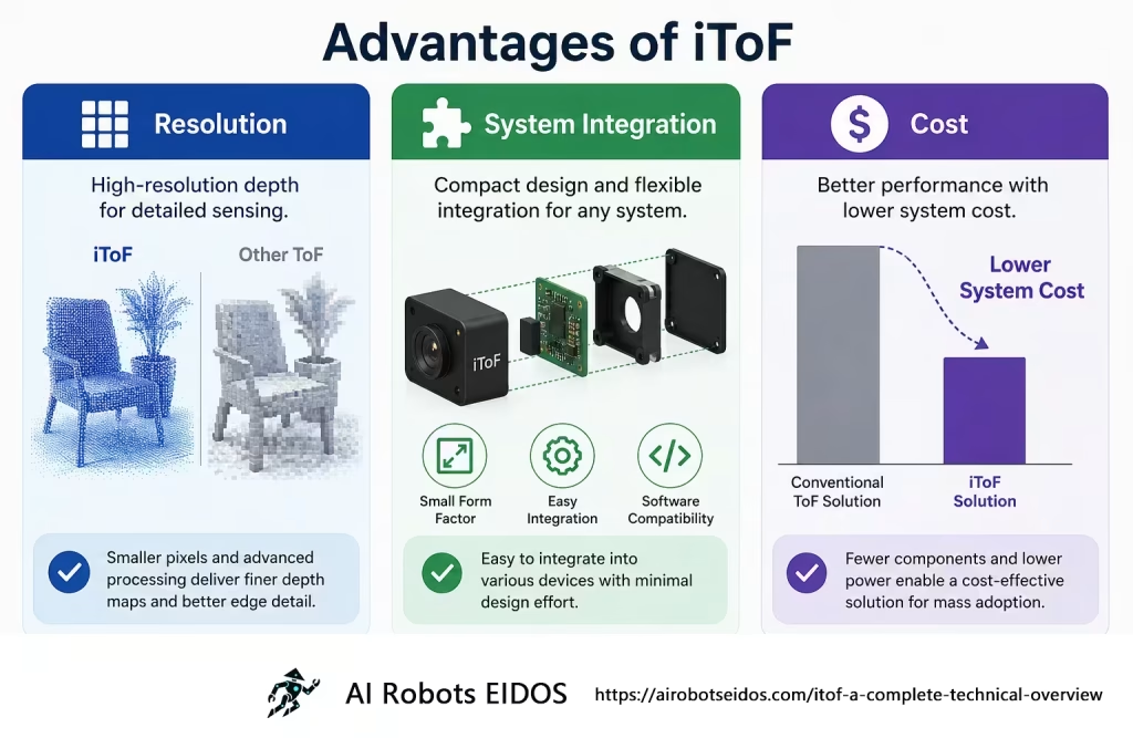
–Cost: The hardware architecture of iToF is relatively simple. The receiver uses standard CMOS processes and does not require the expensive SPAD (Single-Photon Avalanche Diode) and ultra-high-speed TDC (Time-to-Digital Converter) used in dToF, resulting in low overall module cost.
Disadvantages of iToF
–Measurement Distance: Since iToF calculates distance by computing phase, and phase varies within the range of 0–2π, the unambiguous range is limited. For example, if the modulation frequency is 100 MHz, the phase completes one 0–2π cycle every 1.5 meters; at 200 MHz, it completes one cycle every 0.75 meters. At 100 MHz, if a phase offset of 2π is measured, the distance could be 1.5 m, 3 m, 4.5 m, etc. One solution to distance ambiguity is multi-frequency modulation, where several different modulation frequencies are used to confirm the true distance.
In this approach, lower modulation frequencies provide unambiguous distance estimation, while higher modulation frequencies provide greater precision, balancing both measurement range and accuracy. However, this increases computational load and reduces frame rate.
–Accuracy: it calculates distance by measuring the phase difference between emitted and reflected light, and its accuracy is inversely related to the modulation frequency. At close range (e.g., 0–5 meters), accuracy is high (up to centimeter level), but as distance increases, the reflected light intensity decreases and the phase difference change diminishes, causing ranging errors to increase significantly.
–Ambient Light Interference: During the exposure phase of iToF, some ambient light is mixed with the modulated light and received by the sensor, affecting the phase offset calculation. The interference caused by ambient light cannot be distinguished from a single measurement result. The stronger the ambient light, the greater the resulting depth error.
–Power Consumption: Most iToF systems currently use flood illumination. As measurement distance increases, iToF requires higher optical power or longer exposure times to achieve higher accuracy, resulting in higher average power consumption than dToF, which has a certain impact on the battery life of mobile devices.
iToF and Software Filtering
iToF applications typically combine multiple software filtering techniques to improve depth data quality.
| Filter Type | Principle | Function |
| Confidence Filter | Applies a high-pass filter based on a signal strength threshold | Filters out low-confidence pixels to improve data reliability |
| Flying Pixel Filter | Uses edge-aware median filtering combined with a neighborhood depth consistency check | Eliminates suspended artifacts (flying pixels) at object boundaries |
| Temporal Filter | Performs low-pass filtering through multi-frame temporal fusion | Preserves static scene structures |
Applications of iToF
–Service and Logistics Robots: Used for indoor navigation, obstacle avoidance, and human-robot interaction. For example, robotic vacuum cleaners use iToF indoors to build room maps and identify obstacles; warehouse AGVs (Automated Guided Vehicles) use iToF for precise positioning and pallet recognition.
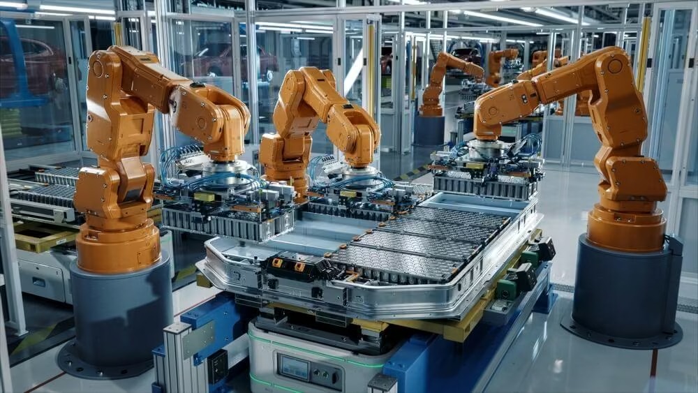
–Industrial Automation: Applied to volume measurement on production lines, robotic arm guidance and sorting, and automated quality inspection.
—Smart Transportation and Construction: Used to monitor passenger flow density at subway platforms or elevator entrances, or to monitor safety conditions around heavy machinery on construction sites.
Common iToF Models
–STMicroelectronics:
VL53L3CX: Emits high-frequency modulated continuous light waves, calculates distance through phase difference. Suitable for short-range high-precision distance measurement and supports multi-object ranging.
VL53L5CX: Uses continuous-wave modulation and histogram algorithms, calculates distance through phase difference, supports multi-zone (e.g., 8×8) ranging. Suitable for short-range high-precision and multi-object ranging.
–Texas Instruments:
OPT3101: High-performance, single-point iToF sensor with strong anti-interference capability.
OPT4048: iToF sensor with integrated ambient light sensor.
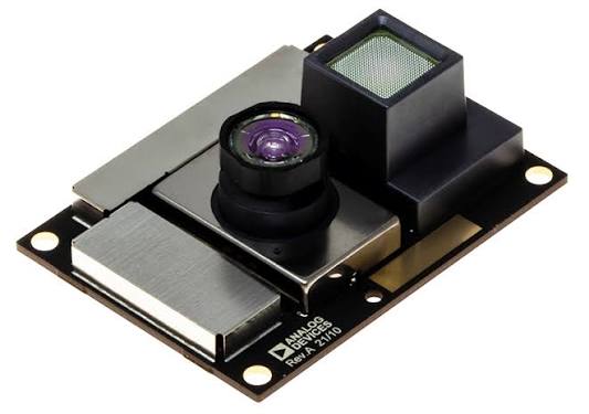
–Analog Devices:
ADTF3175/ADSD3100: High-resolution iToF modules suitable for depth sensing, robot vision, etc.
–Infineon:
REAL3™ Series: Includes IRS2771C, IRS2877A, etc. Primarily used as iToF depth sensors for rear-facing smartphone cameras, such as for face recognition unlocking and background bokeh effects.
Insight from AI Robots Eidos
—Traditionally, iToF has been viewed as a sensor that simply outputs distance data. However, its role will soon go beyond mere ranging: by integrating multi-dimensional outputs such as confidence maps, ambient light estimates, and reflectivity information, it can simultaneously perceive material properties, lighting conditions, and motion states, evolving into a “multimodal perception front-end.”
—Lightweight neural networks can replace traditional look-up-table-based unwrapping algorithms, enabling on-chip real-time multi-frequency fusion and phase unwrapping while simultaneously predicting confidence. This will allow iToF to achieve both long-range (>10 m) and high-precision measurement without sacrificing frame rate, breaking the current bottleneck where range and accuracy are mutually exclusive.
—An adaptive pulse-density modulation (PDM) driver architecture can dynamically adjust transmission power and duty cycle based on scene depth—low power for close-range objects and high power for distant ones—rather than transmitting at constant full power. Combined with the efficiency advantages of multi-junction VCSELs, this approach is expected to reduce power consumption by more than 40% in the future.
—The iToF depth engine can dynamically select filtering strategies and parameters based on scene semantics (e.g., indoor/outdoor, static/dynamic, near/far). For example, it can strengthen flying pixel filtering at edge regions, enhance temporal filtering in flat areas, and skip filtering in high-confidence regions to preserve details, achieving adaptive optimal output across different scenarios.
—The entire pipeline—phase inversion, unwrapping, filtering, and multi-frequency fusion—can be integrated onto the CIS chip using a computing-in-memory (CIM) architecture. This allows depth computation to be completed directly on-chip immediately after pixel readout, outputting a filtered depth map. This approach will significantly reduce both power consumption and latency.
Image Credits: E-consystems & Lumotive & Ibtinc & AI & Analog