Industrial Line Scan Cameras Explained
Table of Contents
Industrial line scan cameras have become one of the core devices in machine vision systems due to their unique principles and performance advantages. They overcome the limitations of traditional area scan cameras in scenarios such as high-speed moving object detection and ultra‑large field‑of‑view imaging, and are widely used in printing, metal processing, new energy, and many other industries.
What Are Industrial Line Scan Cameras?
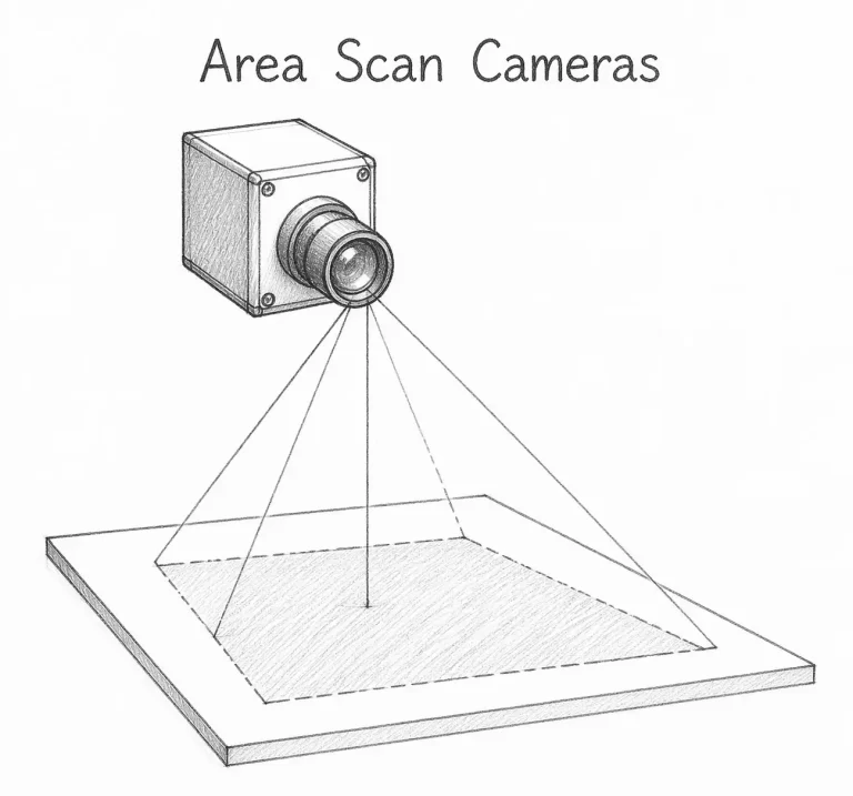
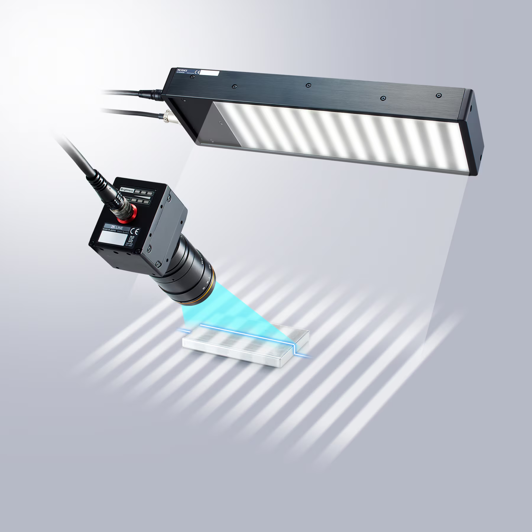
Industrial line scan cameras are a type of two‑dimensional image sensor whose defining feature is a sensor arranged as a “single row of pixels” (typically from 1K to 16K pixels), producing an elongated strip‑shaped field of view. Unlike area scan cameras (which use a rectangular pixel array), an industrial line scan camera relies on relative motion between the camera and the object under inspection. It acquires image data line by line and then stitches these lines into a complete two‑dimensional image.
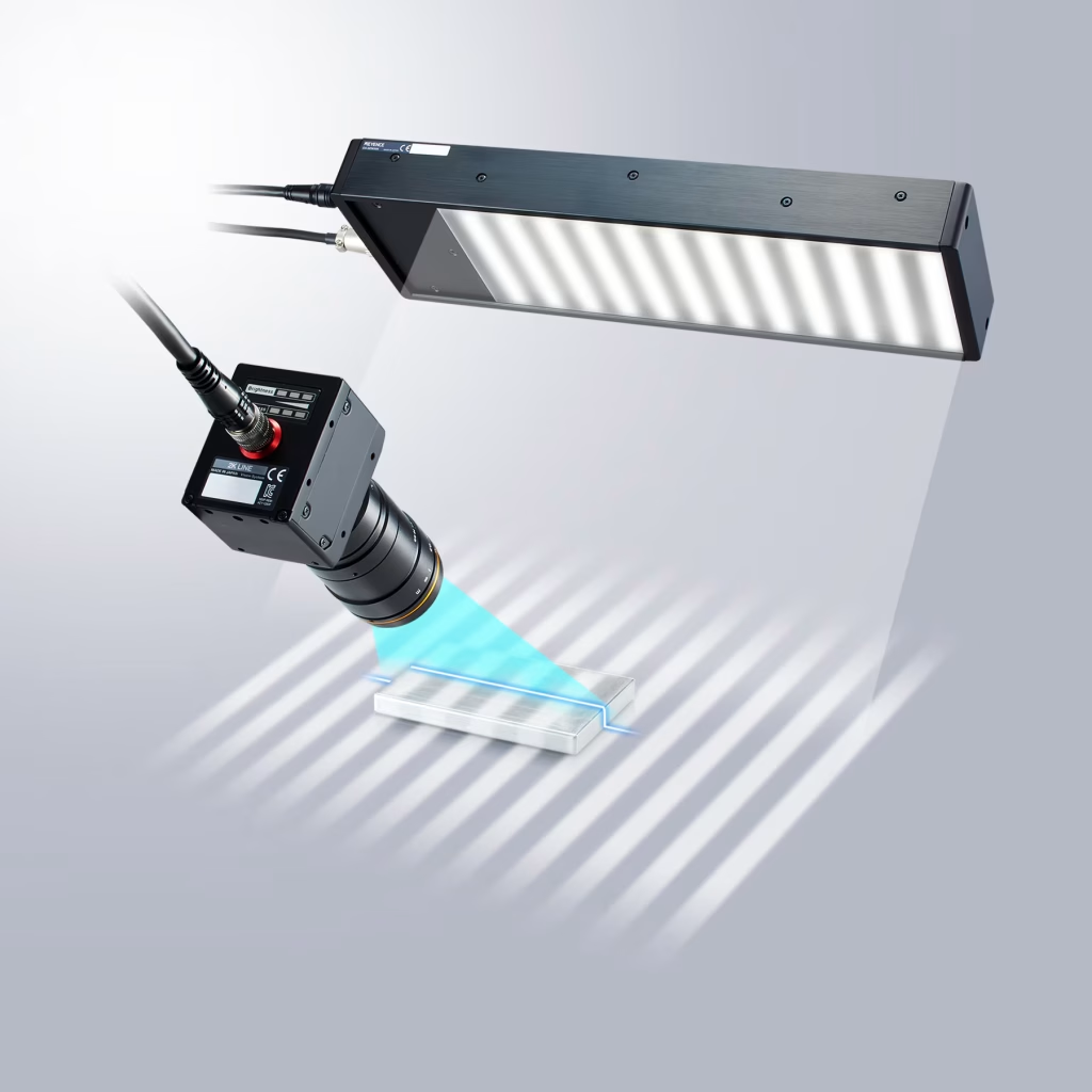
More specifically, during each exposure, an area scan camera (e.g., a typical 4096×3000 sensor) captures an entire image at once. An industrial line scan camera works quite differently: a single exposure captures only one line of the image. If data acquisition software is used while the object is stationary, the resulting image is simply a cumulative stack of the same line repeated over and over. Only when the object moves at a constant speed relative to the camera does the image appear normal.
Recommended In-depth Reading from AI Robots Eidos
Area scan cameras and line scan cameras are two commonly used types of cameras in the field of industrial vision, and they have distinct differences in structure, principles, performance, and application scenarios. Area scan cameras are suitable for static or low-speed scenes and are easy to operate; line scan cameras are suitable for high-speed, large field-of-view, and high-resolution inspections, but the systems are more complex.
If readers wish to learn more about area scan cameras, please read this article on area scan cameras.
Principle of Industrial Line Scan Cameras
–Photoelectric conversion – The image sensor of an industrial line scan camera consists of one or a few rows of pixels, each pixel being a photoelectric sensing element. Common sensor types are CCD and CMOS, which convert light signals into electrical signals. As the object moves at a constant speed, the camera captures light signals line by line at a fixed line rate (lines per second) and converts them into electrical signals via the photoelectric sensors.
–-Signal processing and image composition – The electrical signals are converted into digital signals by a data acquisition board and transmitted via data interfaces (e.g., Camera Link, GigE Vision) to an image processing system. Finally, computer software stitches these line data in sequence to reconstruct a complete 2-Dimensional image.
Classification of Industrial Line Scan Cameras
Classification by Sensor Type
–CCD industrial line scan camera – Uses a charge‑coupled device (CCD) sensor. Offers high image quality and is suitable for applications demanding high image fidelity, such as precision inspection and scientific research, but at a higher cost.
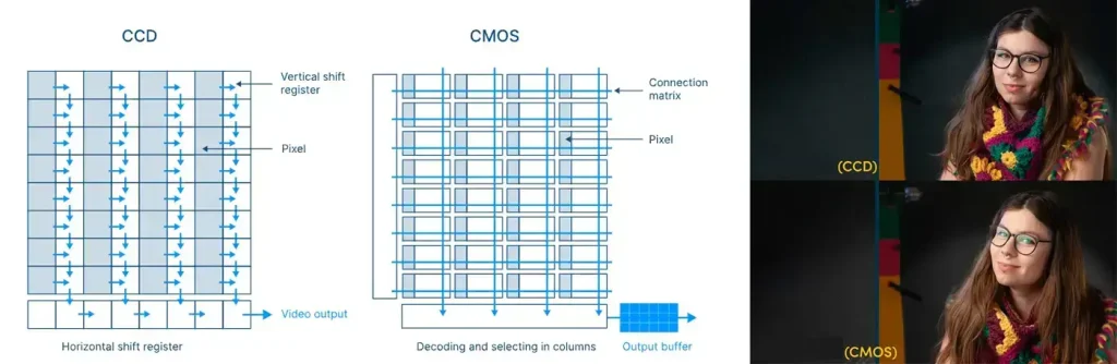
–CMOS industrial line scan camera – Uses a complementary metal‑oxide‑semiconductor (CMOS) sensor. Lower cost, lower power consumption, and faster readout speed. Suitable for high‑speed imaging and cost‑sensitive applications, though image quality is somewhat inferior to CCD sensors.
Classification by Color
–Monochrome (black‑and‑white) industrial line scan camera – Captures only light intensity information, outputting grayscale images. Highly sensitive to light, suitable for detecting grayscale differences and texture details. Commonly used in dimension measurement and defect detection.
–Color industrial line scan camera – Acquires red, green, blue, and other color information to output color images. Used in color‑sensitive inspections such as food appearance inspection, print color inspection, and color sorting.
Classification by Number of Scanning Lines
–Single‑line industrial line scan camera – The sensor has only one row of photosensitive elements. Simple structure, suitable for low‑resolution requirements and slower-moving objects.
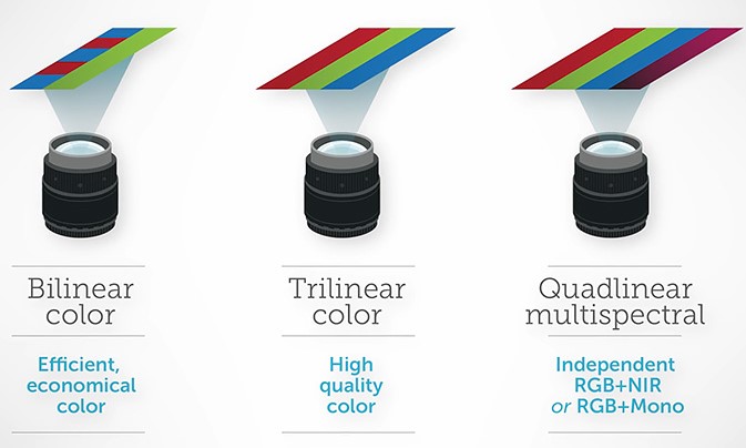
–Dual‑line industrial line scan camera – Uses a two‑row sensor, providing higher sensitivity. Suitable for capturing high‑speed moving objects, often used for surface defect inspection of paper, film, and steel sheets.
–Three‑line industrial line scan camera – Three rows of sensors correspond to RGB color channels, offering good color fidelity. Suitable for high‑speed color inspection applications, but requires spatial correction.
–Multi‑line industrial line scan camera – Such as 4‑line, 6‑line, 8‑line, etc. Improves resolution and sensitivity through multiple sensor rows, suitable for applications demanding extremely high precision and speed.
Classification by Data Interface
–GigE Vision – Based on the Ethernet protocol, long transmission distance and high bandwidth; suitable for remote monitoring and large‑scale data acquisition.
–Camera Link – High transmission speed and stability; suitable for high‑speed imaging and real‑time image processing.
–CoaXPress – Transmits data over coaxial cable, offering long transmission distance and strong anti‑interference capability; suitable for complex industrial environments.
Advantages of Industrial Line Scan Cameras
–High resolution– Because an industrial line scan camera has only a single row of pixels, that row can be made finer, wider, and more uniform without dramatically increasing cost. Typical line scan resolutions are 1024, 2048, 4096, and 8192 pixels, making them suitable for micron‑level precision inspection (e.g., lithium battery electrode defect detection). In contrast, area scan cameras rarely exceed 2048 pixels (common sizes are 640, 768, 1280). For wide‑format, high‑resolution industrial imaging, industrial line scan cameras are more cost‑effective than area scan cameras because a wide field would otherwise require multiple area scan cameras side by side, while a single line scan camera can cover the whole width.
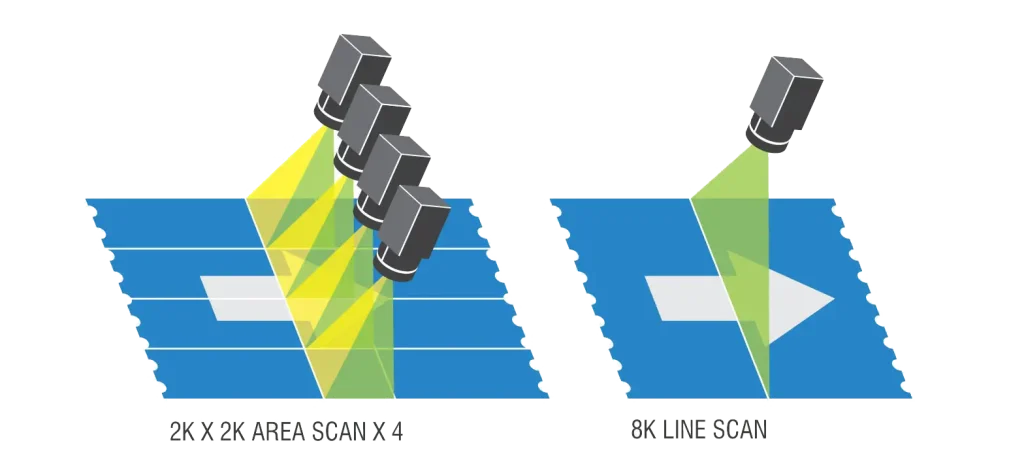
–Faster acquisition speed – Industrial line scan cameras typically acquire at 5,000 – 60,000 lines per second. Users can choose to combine every few lines or every dozen lines into one frame for processing, thus achieving very high frame rates.
–Continuous, uninterrupted acquisition – With line rates up to tens of kHz or even higher and 100% coverage, industrial line scan cameras can continuously acquire images of linearly moving objects (e.g., printed matter, linear guides, fabrics, paper on rollers, objects on a conveyor belt).
–Adaptability to complex scenarios – Flexible mounting allows deployment in tight spaces such as rollers and conveyor belts, enabling surface inspection of cylindrical objects by “unwrapping” the surface. Moreover, compared to area scan cameras, industrial line scan cameras ensure consistent image quality across the entire image without distortion.
Disadvantages of Industrial Line Scan Cameras
To acquire an image with an industrial line scan camera, scanning motion is mandatory. Moreover, to determine the exact position of each pixel on the inspected object, additional components, such as an encoder, are required to record the coordinates of each scanned line. This leads to the following drawbacks:
—Long image acquisition time, resulting in low measurement efficiency.
—The scanning motion and associated position feedback increase system complexity and cost.
—Image accuracy may be degraded by the precision of the scanning motion, ultimately affecting measurement accuracy.
Technical Parameters of Industrial Line Scan Cameras
Core Parameters
| Parameter Name | Core Meaning | Impact on Application Scenarios |
| Resolution | Total number of horizontal pixels on the sensor (e.g., 2K = 2048 pixels, 8K = 8192 pixels) | Determines “horizontal detection accuracy”: more pixels yield higher accuracy for a given width (e.g., for a 1.6m width, a 2K camera gives ≈0.8mm horizontal accuracy) |
| Line Rate | Maximum number of lines that can be acquired per second (unit: line/sec) | Determines whether the camera can keep up with production speed: insufficient line rate results in image stretching/compression (e.g., for a web moving at 2 m/s, line rate ≥ 25,000 lines/sec is required) |
| Max Data Rate | Maximum amount of data that can be output per second (unit: MHz) | Determines transmission hardware cost: a high data rate requires a high‑bandwidth frame grabber (e.g., a 160 MHz data rate requires GigE Vision or CoaXPress interface) |
Other Important Parameters
–Pixel size – The physical size of a single pixel on the sensor (e.g., 5 µm, 7 µm). Affects sensitivity and lens matching. Smaller pixels lead to a smaller sensor size for a given resolution (e.g., for a 2K camera, pixel size 5 µm gives sensor length = 2048×5 µm = 10.24 mm), but lower sensitivity (requiring stronger lighting). Larger pixels provide higher sensitivity, suitable for low‑light conditions.
–Output mode – Single output vs. dual output. Single output sequentially outputs all pixels row by row (e.g., pixels 1 to 8192). Dual output splits the data into two parallel paths (e.g., odd‑numbered pixels on one path, even on the other), increasing line rate at the same data rate – ideal for high‑speed applications.
–Trigger mode – Internal trigger (fixed line rate) and external trigger (line rate controlled by an external signal, e.g., encoder synchronization). Continuous production scenarios must use an external trigger – the encoder provides real‑time web speed to adjust the line rate and avoid image stretching dynamically.
Introduction to Common Multi‑line Technologies for Industrial Line Scan Cameras
–TDI (Time Delayed and Integration): TDI is essentially a scanning technique where a one‑dimensional line array of pixels in the frame transfer device is aligned with and moves synchronously with the object. As the image moves from one row of pixels to the next, the integrated charge also moves, resulting in continuous imaging output of the moving object. Multi‑line industrial line scan cameras use this method to capture the same area of the object multiple times.
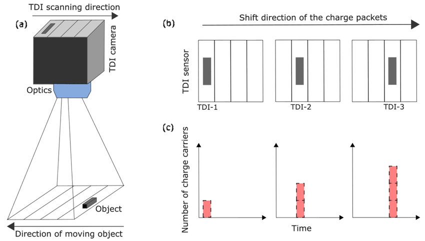
The electrons excited by photons in each row are added to the next row; after several accumulations, the last row has sufficient brightness. This maintains high sensitivity and high speed, and works well in low‑light environments. TDI cameras require strict synchronization between the object’s speed and the camera’s line scan rate; otherwise, image blurring occurs due to improper integration.
–Time‑division strobing: A special line scan method. Unlike constant illumination in traditional line scanning, a time‑division strobe controller switches the type or intensity of the light source with each line acquisition. This orderly interleaves multiple illumination effects in the captured image. After acquisition, the raw image is split and reassembled to obtain images with different lighting effects in a single scan, reducing cost, improving compatibility, and achieving optimal imaging.
–Long/short exposure (High Dynamic Range): By capturing images with different exposure times and then merging them, underexposed areas are brightened (long exposure) while overexposed areas are attenuated (short exposure). The composite image retains light‑sensitive variations across different regions, ensuring clear imaging everywhere. This improves inspection accuracy and avoids interference from varying materials or overlapping structures. This technique can be implemented using line‑triggered mode – for example, odd lines with short exposure, even lines with long exposure – and finally combining the images with software to achieve the desired dynamic range.
Example Industrial Line Scan Camera Products (For Reference Only)
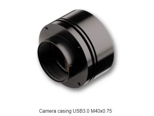
| Resolution (pixels) | Pixel Size (μm) | Max Line Rate (kHz) | Lens Mount | Color | Sensor Type | Bit Depth |
| 4096 | 10×10 | 27.8 | M45×0.75 | Monochrome | CCD | 8/12 |
| 512 | 14×14 | 35.7 | C | Monochrome | CCD | 8/12 |
| 4096 | 10×10 | 11.9 | M45×0.75 | Monochrome | CCD | 8/12 |
| 1024 | 14×14 | 27 | C | Monochrome | CCD | 8/12 |
| 8160 | 5×5 | 11.9 | M45×0.75 | Monochrome | CCD | 8/12 |
| 7500 | 7×7 | 5.2 | M72×0.75 | Monochrome | CCD | 8/12 |
| 7500 | 7×7 | 10.1 | M72×0.75 | Monochrome | CCD | 8/12 |
| 7456 | 4.7×4.7 | 5.2 | M40×0.75 | Monochrome | CCD | 8/12 |
| 5148 | 7×7 | 7.6 | M40×0.75 | Monochrome | CCD | 8/12 |
| 512 | 25×500 | 26.3 | C | Monochrome | CMOS | 8/12 |
| 4096 | 7×200 | 2.4 | M40×0.75 | Monochrome | CMOS | 8/12 |
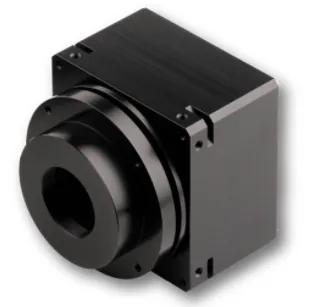
| Resolution (pixels) | Pixel Size (μm) | Max Line Rate (kHz) | Lens Mount | Color | Sensor Type | Bit Depth (bit) |
| 8160 | 5×5 | 11.9 | M72×0.75 | Monochrome | CCD | 8/12 |
| 4096 | 10×10 | 27.8 | M45×0.75 | Monochrome | CCD | 8/12 |
| 2048 | 14×14 | 14 | M45×0.75 | Monochrome | CCD | 8/12 |
| 4096 | 10×10 | 11.9 | M45×0.75 | Monochrome | CCD | 8/12 |
| 2048 | 14×14 | 14 | M45×0.75 | Monochrome | CCD | 8/12 |
| 1024 | 14×14 | 27 | C-Mount | Monochrome | CCD | 8/12 |
| 8160 | 5×5 | 11.9 | M45×0.75 | Monochrome | CCD | 8/12 |
| 7500 | 7×7 | 5.2 | M72×0.75 | Monochrome | CCD | 8/12 |
| 7500 | 7×7 | 8.3 | M72×0.75 | Monochrome | CCD | 8/12 |
| 7456 | 4.7×4.7 | 5.2 | M45×0.75 | Monochrome | CCD | 8/12 |
| 5148 | 7×7 | 7.6 | M45×0.75 | Monochrome | CCD | 8/12 |
How To Choose Line Scan Cameras?
Selection Process:
Calculate required resolution: Pixels per row = width / minimum detection accuracy.
Select camera: Actual detection accuracy = width/number of pixels.
Determine line rate: Required lines per second = object speed (mm/s) / accuracy.
Example:
Conditions: Width = 1600 mm, minimum detection accuracy = 1 mm, speed = 26,000 mm/s.
Camera selection:
Required resolution = 1600/1 = 1600 pixels → at least 2000 pixels → choose a 2K camera.
Actual detection accuracy = 1600/2048 ≈ 0.8 mm.
Required line rate = 26,000 mm/s / 0.8 mm = 32,500 lines/s (32.5 kHz).
Therefore, select a camera with 2048 pixels and at least 33 kHz line rate.
Precautions When Selecting An Industrial Line Scan Camera:
Do not blindly pursue higher pixel counts. Adequate is enough; excess pixels increase lens cost (higher pixel counts require larger sensors, more expensive lenses) and data processing load.
Do not overlook line rate margin. Choose a model with a line rate at least 20% higher than the calculated value to avoid image stretching due to production speed fluctuations.
Do not skip laboratory testing. Real‑world conditions (vibration, dust, lighting interference) can be harsh; first, validate the solution in the lab, then proceed to field testing.
Applications of Industrial Line Scan Cameras
—Typical applications involve inspecting continuous materials such as metals and plastics. The object moves at a constant speed while one or more cameras scan line by line to uniformly inspect the entire surface. The image can be processed line by line or as a 2D image composed of multiple lines. Examples include:
Metal sheet inspection – Detecting scratches, cracks, dents, rust, and other defects on steel plates, aluminum sheets, etc., covering wide formats at high speed.

Plastic film and web inspection – Inspecting films, paper, fabrics, rubber webs for surface flaws such as stains, holes, wrinkles, and thickness variations – essential for quality control on continuous production lines.
Print quality inspection – Checking color accuracy, registration precision, text clarity, and pattern integrity of printed materials, enabling timely detection of print defects.
—In recent years, advances in CMOS and CCD sensor technology have brought breakthroughs in imaging speed, resolution, and sensitivity for industrial line scan cameras. As key components of machine vision, industrial line scan cameras are also being deployed in automated sorting, logistics inspection, traffic monitoring, and other fields where machine vision is expanding.
However, it should be noted that industrial line scan cameras have relatively high procurement and integration costs. Moreover, applying industrial line scanning requires sophisticated optical systems, data processing software, and control systems, demanding substantial technical expertise from the user. These factors may hinder the adoption of the technology by small and medium‑sized enterprises.
Future Development Directions of Industrial Line Scan Cameras
As an important technology in machine vision, industrial line scan cameras are evolving in the following directions:
–Higher resolution and higher speed – Driven by increasing demands for precision and efficiency in industrial inspection, industrial line scan cameras are moving toward higher resolutions (e.g., 8K, 12K pixels and beyond) and higher line rates (hundreds of kHz, even MHz) to meet the needs of high‑speed scanning of wide materials and detection of tiny defects.
–Multispectral and multimodal imaging – Integrating multispectral filter arrays or using TDI (Time Delay Integration) technology to enable simultaneous multi‑band acquisition. This allows the camera to capture both spectral characteristics and spatial information of target objects, with applications in agricultural monitoring, semiconductor inspection, environmental monitoring, etc., thereby increasing inspection dimensionality and accuracy.
–Intelligence and edge computing – Embedding AI algorithms and edge computing capabilities into the camera itself to perform real‑time image analysis, defect recognition, classification, and other functions. This reduces reliance on back‑end processing systems, improves inspection efficiency and response time, and meets the real‑time demands of smart manufacturing scenarios.
Insight from AI Robots Eidos about Industrial Line Scan Cameras
Future industrial line scan cameras will no longer be merely image acquisition devices; they will evolve into independent “visual inspection units” that can perform defect identification, classification, and even exclusion control in real time. This evolution will eliminate the dependence on industrial control computers or backend servers, achieving truly distributed intelligent detection.
Currently, defect detection relies on a large number of labeled samples. In the future, by integrating multimodal large models, industrial line scan cameras will be able to identify previously unseen defect types based solely on textual descriptions (such as “scratch” or “hole”). This capability will significantly shorten the debugging cycle for new product production lines, making them particularly suitable for flexible manufacturing and customized production scenarios.
Real-time mapping of the high-precision images collected by line scan cameras to digital twin models will allow for the comparison of differences between the design model and the physical entity. This approach will enable reverse control of production parameters (such as tension and speed), forming a closed-loop intelligent production system characterized by “detection-analysis-adjustment.”
Image Credits: Avatech & Web & Hikrobotics & Teledynevisionsolutions & Keyence & Researchgate & Baslerweb & Mpb