Area Scan Cameras
Table of Contents
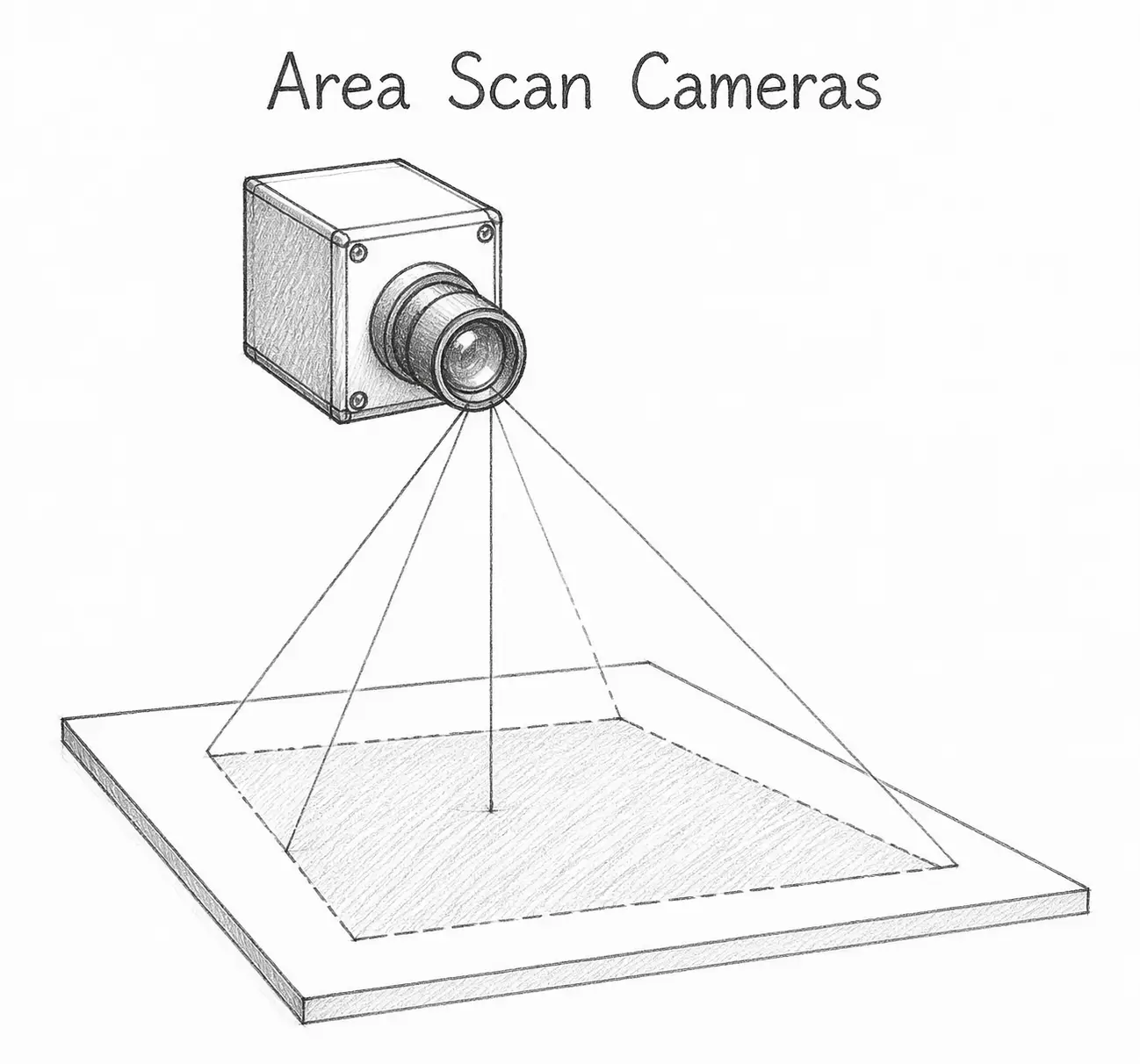
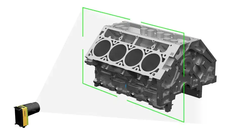
Area scan cameras acquire images in a two‑dimensional area format. It can capture a complete target image in a single exposure and perform image acquisition promptly. It plays a vital imaging role in applications such as determining the shape, size, and position of target objects.
What Are Area Scan Cameras?
Area scan cameras mainly use a continuous, area‑scanning light beam to inspect products. They can capture a complete target image in a single shot and acquire images instantly.
The imaging principle of an area scan camera is similar to that of a mobile phone or digital camera. At the moment the shutter opens, the entire sensor plane is exposed simultaneously, outputting a complete two‑dimensional image in one go.
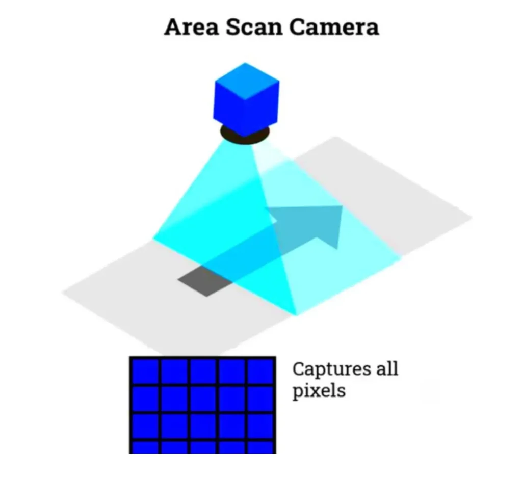
Area scan camera systems, such as RGBD cameras, are extremely simple to set up, have low synchronisation requirements, and offer intuitive software processing. They are therefore very suitable for static or low‑to‑medium speed capture.
Principle of Area Scan Cameras
–Optical imaging: The lens collects light reflected or transmitted by the object and focuses it onto the image sensor. Parameters such as focal length and aperture determine the field of view, depth of field, and brightness of the image.
–Photoelectric conversion: The image sensor (commonly CCD or CMOS) converts the optical signal into an electrical signal. Taking a CMOS sensor as an example: each pixel has a photodiode that generates charge proportional to the light intensity when illuminated; this charge is then converted into a voltage signal.
–Signal readout and processing: The converted electrical signal is amplified and then digitised by an analogue‑to‑digital converter (ADC). The resulting digital signal is processed by image processing circuits (gain adjustment, colour correction, etc.) to produce the final digital image data.
–Image output: The processed image data is transmitted to a computer or image acquisition device via an interface (e.g., GigE, USB, Camera Link) for subsequent analysis, display, or storage.
Types of Area Scan Cameras
Area scan cameras are classified according to the structure or arrangement of their image sensor, each type having its own characteristics.
Frame Transfer Area Scan Cameras
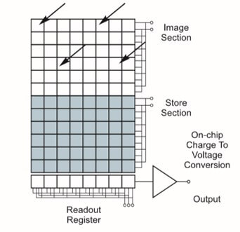
The CCD image sensor of a frame transfer camera consists of three parts: an imaging region, a storage region, and a horizontal shift register. The imaging region is composed of several parallel charge‑coupled channels. The storage region has the same structure and number of cells as the imaging region, and both the storage region and the horizontal shift register are shielded by aluminium.
Frame transfer cameras are characterised by simple structure, high fill factor, and high well capacity, but their shutter speed is not particularly fast.
Interline Transfer Area Scan Cameras
In interline transfer cameras, the imaging elements of the CCD sensor are arranged in a two‑dimensional array. Each column of imaging elements is separated by a light‑shielded readout register and channel stops. A transfer control gate is placed between the imaging elements and the readout register.
Interline transfer cameras operate under the PAL television standard, ultimately producing a video signal at the output that corresponds to the optical image. Compared to frame transfer cameras, they have faster transfer speeds but lower pixel density.
Line Transfer Area Scan Cameras
Compared to the previous two types, the line transfer area scan camera eliminates the storage region and adds a line addressing circuit. Its imaging elements are arranged row by row, tightly packed into an area array, similar to the imaging region of a frame transfer CCD, but each row has a specific address.
Line transfer cameras offer advantages such as a large effective photosensitive area, high transfer speed, and high transfer efficiency. However, the relatively complex circuit limits their range of applications.
Full‑Frame Transfer Area Scan Cameras
The CCD image sensors of full‑frame transfer cameras have a much simpler structure: they have neither a storage region nor a vertical shift register. They provide the highest fill factor, as each pixel can both collect photocharge and perform charge transfer.
The greatest feature of full‑frame transfer cameras is their small size and potential for miniaturisation, making them very suitable for medical and industrial electronic endoscopes.
Important Parameters of Area Scan Cameras
–Exposure time: The time interval between the shutter opening and closing, during which the camera’s pixels receive photons.
–Pixel size: The physical size of one pixel in the camera.
–Sensor resolution: The number of pixels the camera contains, usually expressed as width × height.
–Frame rate: The number of images output by the camera per second.
–Quantum efficiency: An important parameter describing the photoelectric conversion capability of a device – the ratio of the average number of photoelectrons generated per unit time to the number of incident photons at a given wavelength.
–Readout rate: Represents the speed at which the camera can read out part of an image or multiple pixels simultaneously to increase readout speed. Two rates are often defined: the full‑frame readout rate and the maximum readout rate.
Selection Guide for Area Scan Cameras
Selecting an area scan camera requires a trade‑off among resolution, frame rate, sensor type, interface, lens matching, and other factors, while considering the specific application requirements.
–Define application needs:Understand your own requirements, including the inspection target (e.g., defects, colour, texture) and the required precision. Also consider the application scenario – static inspection (e.g., product appearance) or dynamic capture (e.g., moving objects) – as well as environmental conditions (illumination, temperature, etc.).
–Determine resolution: Calculate the required resolution based on inspection accuracy and field of view. It is advisable to add a margin to account for edge distortion or to improve detection stability.
Resolution = (Field width / Accuracy) × (Field height / Accuracy)
Example: To inspect a 10mm × 10mm object with 0.01mm accuracy, the resolution must be at least 1000 × 1000 pixels.
–Select sensor type
CCD: High image quality – suitable for static inspection or low‑light environments where image quality is critical.
CMOS: Low cost, low power consumption, high frame rate – suitable for dynamic inspection or cost‑sensitive applications.
–Determine frame rate: For static inspection, the frame rate only needs to meet the inspection cycle. For dynamic inspection, the frame rate must exceed the capture frequency corresponding to the object’s speed – typically a margin of 1.2 to 2 times is kept. Note the trade‑off between frame rate and resolution; high‑resolution cameras often have lower frame rates.
–Select interface type
GigE: Long transmission distance (up to 100m), low cost – suitable for low‑to‑medium frame rate and resolution.
USB 3.0: Fast transfer speed, flexible deployment – suitable for most industrial scenarios.
Camera Link or CoaXPress: High bandwidth – suitable for high‑resolution, high‑frame‑rate, high‑end applications.
–Consider lens matching: Ensure the lens interface (e.g., C‑mount, CS‑mount) matches the camera. Also consider lens distortion, depth of field, etc. Calculate the focal length using:
Focal length = (Working distance × Sensor size) / Field width
Example: Working distance 200 mm, sensor width 8mm, field width 100mm → focal length ≈ 16mm.
–Evaluate other parameters
Pixel size: A larger pixel size gives better sensitivity but may reduce resolution; choose according to lighting conditions and detection needs.
Bit depth: 8 or 12 bits is sufficient for most industrial applications. Higher bit depth gives more image detail but increases data volume.
Trigger mode: Choose external or internal trigger based on application needs. An external trigger is suitable for use with sensors or mechanical devices.
Example Parameters of Area Scan Cameras
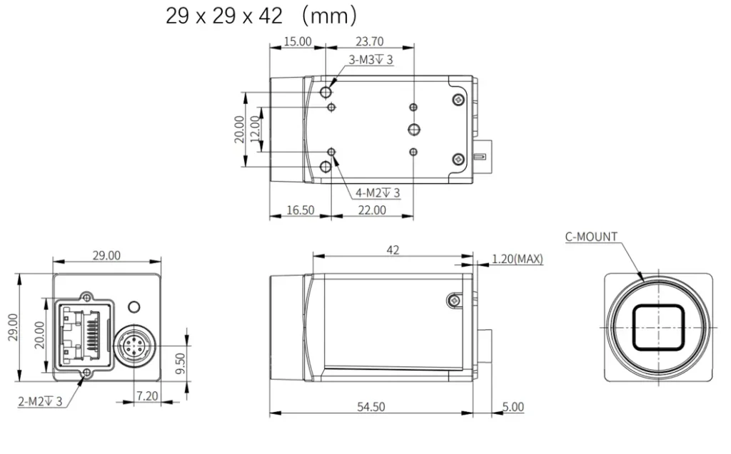
| Resolution (H×V) | Sensor Size | Frame Rate (FPS) | Data Interface | Mono/Color | Shutter Type | Dimensions (mm) |
| 720×540 | 1/2.9″ | 303.21 | GigE PoE | Mono | Global | 29×29×42 |
| 720×540 | 1/2.9″ | 303.21 | GigE PoE | Color | Global | 29×29×42 |
| 1280×1024 | 1/2.7″ | 89 | GigE PoE | Mono | Global | 29×29×42 |
| 1280×1024 | 1/2.7″ | 89 | GigE PoE | Color | Global | 29×29×42 |
| 1440×1080 | 1/2.5″ | 75 | GigE PoE | Mono | Global | 29×29×42 |
| 1440×1080 | 1/2.5″ | 75 | GigE PoE | Color | Global | 29×29×42 |
| 1600×1200 | 1/2″ | 58.6 | GigE PoE | Mono | Global | 29×29×42 |
| 1600×1200 | 1/2″ | 58.6 | GigE PoE | Color | Global | 29×29×42 |
| 2592×1944 | 1/2.5″ | 23.38 | GigE PoE | Mono | Rolling | 29×29×42 |
| 2592×1944 | 1/2.5″ | 23.38 | GigE PoE | Color | Rolling | 29×29×42 |
| 2448×2048 | 2/3″ | 23.5 | GigE PoE | Mono | Global | 29×29×42 |
| 2448×2048 | 2/3″ | 23.5 | GigE PoE | Color | Global | 29×29×42 |
| 4024×3036 | 1/1.7″ | 9.6 | GigE PoE | Mono | Rolling | 29×29×42 |
| 4024×3036 | 1/1.7″ | 9.6 | GigE PoE | Color | Rolling | 29×29×42 |
| 5472×3648 | 1″ | 5.9 | GigE PoE | Mono | Rolling | 29×29×42 |
| 5472×3648 | 1″ | 5.9 | GigE PoE | Color | Rolling | 29×29×42 |
Recommended In-depth Reading from AI Robots Eidos
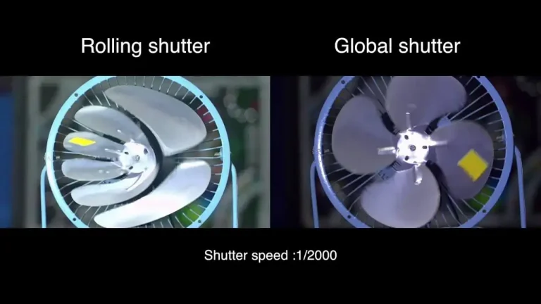
In the specifications of area array cameras, you may notice two options: “global shutter” and “rolling shutter.” What are the differences between them? Simply put, a global shutter allows all pixels to be exposed simultaneously, making it suitable for capturing high-speed moving objects; whereas a rolling shutter exposes the image row by row, offering better image quality in static or low-speed scenes. Choosing the wrong shutter type can lead to distortion of moving objects or image blur.
Interested readers can refer to this article on rolling shutter vs global shutter, helping to avoid common pitfalls in selection.
Applications of Area Scan Cameras
The core advantage of area scan cameras is their ability to quickly acquire complete image information, making them suitable for inspection, measurement, and recognition tasks on static or low‑speed moving objects.
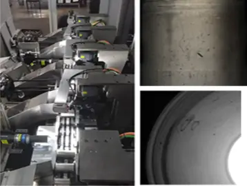
–Defect detection: Accurately identify defects on workpiece surfaces, shapes, and contours. Using deep‑learning technology, they can detect fine surface scratches and spots, overcoming interference from workpiece texture, colour, etc.
For example, eight 5‑megapixel area scan cameras combined with multiple types of light sources perform full inspection of product appearance, solving the detection of various defects on multiple products.
–Positioning and measurement: Precisely and efficiently locate any geometric element in an image – quickly and accurately find the positions of circles, lines, spots, edges, vertices, etc. Precisely measure shapes, sizes, areas, distances, angles, intersections, and other geometric features. Provide position and presence information applicable to robot guidance and other vision tools.
Insight from AI Robots Eidos about Area Scan Cameras
—Combining Event-based Vision and programmable pixel timing, area array cameras can dynamically adjust the exposure start time and duration for each row or even each pixel, achieving “asynchronous but coherent” capture of high-speed moving objects. This “smart pixel timing” technology can reconstruct sub-millisecond time resolution through algorithms without increasing hardware frame rates, enabling existing low to mid-frame-rate area array cameras to handle ultra-fast transient process analysis.
—In the future, imaging with area array cameras will move away from “capture then process” to end-to-end differentiable imaging. The optical parameters of the lens (focal length, aperture) and the sensor’s pixel layout will be jointly encoded into a trainable neural network front end. The camera will directly output high-level feature maps instead of raw images, significantly reducing data transmission bandwidth and backend computational pressure. For example, in defect detection tasks, the camera will directly output “defect probability heat maps” rather than raw images with millions of pixels.
—The next generation of area array cameras will be equipped with lightweight neural network acceleration chips (NPU/TPU), becoming edge nodes with autonomous perception and decision-making capabilities. The camera will not only output images but also real-time detection conclusions, trigger signals, or control commands. For instance, on high-speed packaging lines, the area array camera will directly determine whether a product is qualified and, through built-in I/O, remove defective products with a delay of less than 1 millisecond. At the same time, the camera can dynamically adjust exposure parameters, ROI areas, and even operating modes based on detection results to achieve closed-loop adaptive perception.
Image Credits:Intelgic & Web & Cognex & Optixs & AI