
Table of Contents
Visual SLAM, also known as vision SLAM, refers to the technology that enables a device to rely solely on visual sensors to simultaneously “know where it is” and “build a map of the surrounding environment” in unknown environments. It is a key technological foundation for autonomous navigation and environmental perception in fields such as robotics and autonomous driving.
What is SLAM?
SLAM, which stands for Simultaneous Localization and Mapping, refers to the process in which an autonomous device without prior environmental information (e.g., a robot, drone, etc.) uses only its onboard sensors during motion in an unknown environment to simultaneously estimate its own trajectory (localization) and build a consistent map of the surrounding environment (mapping).
Recommended In-depth Reading from AI Robots Eidos
The core idea of SLAM (Simultaneous Localization and Mapping) is to “simultaneously determine one’s own position and construct a map of the environment in an unknown setting.” Visual SLAM is a subset of SLAM that focuses on using cameras as sensors to achieve this goal. Understanding the basic concepts of SLAM is a prerequisite for a deeper understanding of visual SLAM.
Interested readers can refer to this article about Simultaneous Localization and Mapping.
What is Visual SLAM?
When the sensor used in an autonomous device’s SLAM system is a visual sensor (e.g., a camera), we call it visual SLAM. The core of visual SLAM is to achieve simultaneous localization and mapping using visual sensors. Among these, the camera, as one type of visual sensor, offers low cost and rich information (color, texture, shape, etc.), making it one of the most popular research directions in visual SLAM.
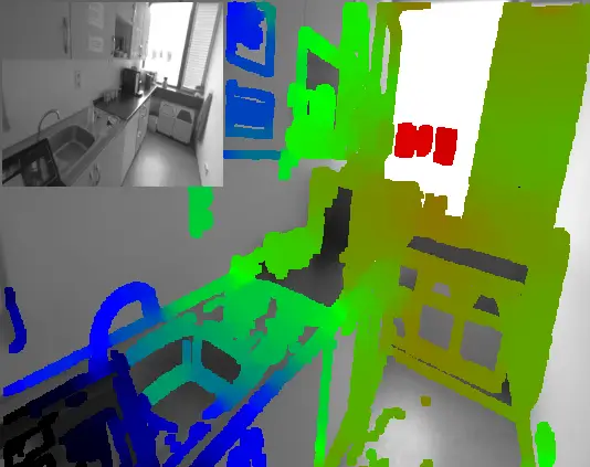
Visual SLAM iteratively processes image data, combining techniques such as feature extraction, matching, pose estimation, and optimization algorithms to gradually refine localization and map construction, enabling devices to navigate and perceive the surrounding world in unknown environments autonomously.
Principles of Visual SLAM
Visual SLAM works by tracking key points across consecutive camera frames, localizing them using triangulation, and using this information to estimate the camera’s own pose. In simple terms, the goal of these systems is to map the environment relative to the device’s own position. This map can then be used for navigation within that environment. Unlike other forms of SLAM, visual SLAM requires only a single 3D vision camera.
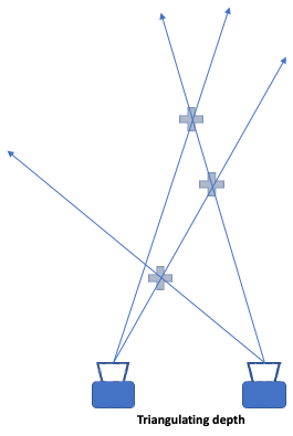
By tracking a sufficient number of key points across camera video frames, the system can quickly understand the sensor’s orientation and the structure of the surrounding physical environment. All visual SLAM systems continuously work to minimize the reprojection error—the difference between projected points and actual points—typically using the Bundle Adjustment (BA) algorithm. Because visual SLAM involves heavy computation, positional and mapping data are often separated but undergo Bundle Adjustment simultaneously to speed up processing before final merging.
Classification of Visual SLAM
By Sensor Type
–Monocular SLAM: The monocular SLAM uses only a single camera to perform SLAM. Its main advantage is simplicity and low cost, but it suffers from the inability to obtain depth information (distance) from a single image, leading to scale ambiguity.
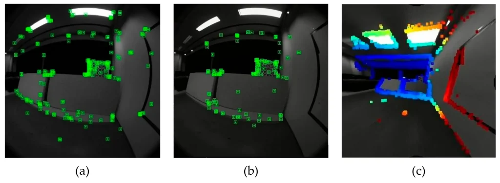
–Stereo SLAM: The stereo SLAM uses the disparity between left and right images to compute pixel distances for localization. Stereo vision can estimate depth both during motion and while stationary, eliminating the depth information problem of monocular vision. However, computing pixel distances from stereo images is computationally intensive, and tracking is easily lost in low-texture environments like white walls or in low-light conditions.
–RGB-D SLAM: An RGB-D camera outputs both RGB images and corresponding depth maps. Instead of time-consuming passive stereo matching, pixel depth is measured by projecting laser speckle to increase texture for faster computation or via hardware measurement (structured light, ToF, etc.). RGB-D SLAM more directly captures the 3D structure of the scene, reducing the complexity of mapping and localization, especially in indoor environments, where it offers high accuracy and practicality. However, RGB-D sensors have a short range and tend to fail in strong outdoor light.
–VIO / VI-SLAM: The VIO / VI-SLAM is a simultaneous localization and mapping technology that fuses data from visual sensors and inertial measurement units (IMUs). By processing both camera-captured image data and inertial data (acceleration, angular velocity) from the IMU, VIO enables real-time position and attitude estimation for an autonomous device in unknown environments, along with mapping of the surroundings.
By Front-End Processing Method
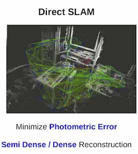
–Direct Method: The direct method does not extract feature points but directly uses pixel intensity information, assuming that the intensity of corresponding pixels remains constant between consecutive frames, and estimates camera pose by minimizing a photometric error function. It requires no feature extraction, runs fast, adapts well to low-texture scenes, and can build semi-dense or dense maps. However, it is sensitive to sudden illumination changes and exposure variations; large disparity or fast motion can easily cause tracking loss, and its loop closure detection and global optimization capabilities are relatively weak.
–Indirect Method: The indirect method extracts feature points from images (e.g., SIFT, ORB, FAST), computes feature descriptors, matches them, and estimates relative camera motion from matched features. It is robust to illumination changes, rotation, and motion blur, making it suitable for large-scale mapping. However, it relies heavily on image features, fails in low-texture or repetitive texture areas, and feature extraction/matching is time-consuming; the map is usually a sparse point cloud.
By Back-End Processing Method
–Filtering Method: The filtering method assumes that the system state satisfies the Markov property—the current state depends only on the previous state—and recursively computes the posterior probability of the state, gradually updating pose and map information. Filtering methods have relatively low computational requirements and strong real-time performance, making them suitable for resource-constrained embedded systems. However, they are prone to accumulating errors over long-term operation and have weaker capabilities for loop closure detection and large-scale scene handling.
–Nonlinear Optimization Method: The nonlinear optimization method considers all historical observations, constructs a global cost function, and simultaneously optimizes camera poses and map point positions by minimizing reprojection errors or observation residuals. This method achieves high global consistency, effectively handles loop closure detection and large-scale scenes, and offers higher localization accuracy. However, it is computationally intensive and requires techniques like keyframe selection and sparse matrix optimization to reduce complexity.
Visual SLAM Algorithms
Algorithms by Sensor Type
| Type | Representative Algorithms | Accuracy | Key Advantages | Key Disadvantages |
| Monocular Visual SLAM | PTAM, MonoSLAM, ORB-SLAM1, DSO (monocular version) | No absolute scale; only relative localization with centimeter-to-decimeter accuracy; scale drift tends to occur over long-term operation. | Extremely low sensor cost, small size, low power consumption, simple hardware setup, easy integration into small inspection devices. | Inherent scale ambiguity; must rely on device motion to recover depth; cannot measure distance when stationary; pure rotational motion easily causes tracking loss; poor stability in low-texture environments. |
| Stereo Visual SLAM | ORB-SLAM2, SVO, LSD-SLAM | True absolute scale; stable centimeter-level localization accuracy; outperforms monocular in outdoor long-distance scenes. | Directly computes true depth without motion, solving the monocular scale problem; strong adaptability to outdoor environments; suitable for large-scale mapping. | Complex camera calibration and time synchronization; fixed stereo baseline causes a significant drop in depth accuracy for distant objects; difficult matching in low-texture or repetitive texture areas; higher computational load than monocular. |
| RGB-D SLAM | KinectFusion, ElasticFusion, ORB-SLAM2 (RGB-D mode) | Indoor dense reconstruction accuracy up to millimeter-centimeter level; centimeter-level localization accuracy. | Directly outputs dense depth maps; fast and effective 3D mapping; excellent indoor localization and reconstruction performance. | Short range (typically 0.5–5 m); depth information completely fails under strong outdoor light; sensitive to reflective, black, or transparent objects, leading to depth missing. |
| VIO / VI-SLAM | VINS-Mono, VINS-Fusion, OKVIS, MSCKF | Best overall accuracy; centimeter-level localization; remains stable in dynamic and fast-motion scenarios. | Fuses visual and IMU data; vision ensures long-term stable localization while IMU compensates for high-frequency motion and occlusions; completely solves the monocular scale problem; maximizes anti-interference and robustness. | Difficult intrinsic/extrinsic calibration and multi-sensor time synchronization; high computational load for coupled optimization; requires higher hardware computing power. |
Algorithms by Front-End Processing
| Method | Representative Algorithms | Accuracy | Key Advantages | Key Disadvantages |
| Indirect Method | ORB-SLAM series, PTAM, FABMAP | High localization accuracy; stable loop closure; overall centimeter level. | Robust to illumination changes, rotation, and motion blur; good long-term consistency; suitable for large-scale mapping. | Highly dependent on image features; fails easily in low-texture or textureless areas (e.g., smooth concrete surfaces of bridges); feature extraction and matching are time-consuming, limiting high frame rate operation. |
| Direct Method | DSO, LSD-SLAM, SVO | Good semi-dense reconstruction accuracy; centimeter-to-decimeter localization. | No feature extraction required; uses pixel intensity directly for localization; better adaptability to low-texture scenes than feature-based methods; fast operation; supports high frame rates. | Sensitive to sudden illumination and exposure changes; tracking loss is likely under large disparity or fast motion; weaker loop closure detection and global optimization capabilities. |
Algorithms by Back-End Processing
| Method | Representative Algorithms | Accuracy | Key Advantages | Key Disadvantages |
| Filtering Method | EKF-SLAM, UKF, particle filter, MSCKF | Acceptable short-term accuracy; significant long-term drift; decimeter level. | Low computational cost; strong real-time performance; suitable for low-power embedded devices. | Maintains only the current state; discards historical information; poor consistency in large scenes; difficult to achieve effective loop closure. |
| Nonlinear Optimization Method | g2o- and Ceres-based ORB-SLAM, VINS | Best global consistency; centimeter level; no significant drift over long-term operation. | High global optimization accuracy; effective loop closure; perfectly suited for large-scale, long-duration mapping and localization. | High computational cost; requires sliding windows and keyframe strategies to control complexity; demands high hardware computing power. |
Workflow of Visual SLAM
Visual SLAM is the process of using a camera as a sensor to localize itself while simultaneously building a map of the environment. The entire workflow is generally divided into five modules: sensor data reading, visual odometry, back-end optimization, loop closure detection, and mapping.
—Sensor Data Reading refers to acquiring images or data from sensors and performing preprocessing such as distortion removal. A sensor is a device that perceives external information and converts it into usable electrical signals or other forms of output according to certain rules.
—Visual Odometry is a technique that uses a camera as a sensor to simultaneously localize and map unknown environments. The basic idea is to estimate camera motion and local map structure based on feature matching between consecutive images.
—Back-End Optimization refers to globally optimizing camera poses and map points in a visual SLAM system to eliminate accumulated errors and improve global consistency. Back-end optimization can be viewed as a state estimation problem—finding the optimal estimate of the system state given observations.
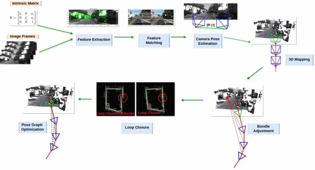
—Loop Closure Detection determines whether a robot has returned to a previously visited location. If a loop closure is detected, it provides constraint information to the back-end optimizer to correct accumulated errors and close the map. Loop closure detection is one of the challenges of visual SLAM, requiring fast and accurate matching across a large number of images.
—Mapping refers to building a map according to task requirements using optimized camera trajectories and map points. Maps can take various forms, such as sparse point clouds, dense point clouds, mesh models, semantic labels, etc. Mapping is one of the applications of visual SLAM, providing a foundation for navigation, planning, augmented reality, and more.
Future Directions of Visual SLAM
In the development of SLAM, the fusion of different technologies is the mainstream direction. Therefore, in terms of technological development, this includes both LiDAR SLAM and visual SLAM—readers should take note.
Recommended In-depth Reading from AI Robots Eidos
LiDAR SLAM and visual SLAM are two main technological routes within SLAM (Simultaneous Localization and Mapping) technology. LiDAR SLAM and visual SLAM are not mutually exclusive; rather, they promote the advancement of SLAM technology in fields such as robotic navigation through their complementarity, integration, and collaborative development.
Interested readers can refer to this article about LiDAR SLAM.
–Multi‑Sensor Deep Fusion: The figure below shows a proposed multi‑sensor fusion environment perception system based on LiDAR SLAM and visual SLAM, including 2D grid maps, 3D point cloud maps, etc. The future trend is to fuse more types of sensors, such as infrared cameras, acoustic sensors, IMUs, etc., to obtain richer perceptual information, thereby improving localization accuracy and robustness under various extreme conditions.
–Algorithm Optimization: Deep application of deep learning: Neural networks will play a greater role in environmental adaptability, data processing, and feature extraction.
–Tighter coupling: Current LiDAR SLAM and visual SLAM technologies mostly use loosely coupled methods. Future research should focus on how to achieve tighter sensor fusion to improve the accuracy and reliability of state estimation.
–Introduction of reinforcement learning: Integrate reinforcement learning techniques to study adaptive SLAM systems that can dynamically modify algorithm parameters according to environmental changes, thereby improving system stability and adaptability.
–Real‑time Performance Improvement: To meet the demands of real‑time applications, engineers are working to improve the computational efficiency of SLAM algorithms. For example, the SplaTAM framework, which uses explicit volumetric data representation, achieves high‑fidelity reconstruction from a single uncalibrated RGB-D camera, improving the system’s real‑time performance.
Insight from AI Robots Eidos about Visual SLAM
–Ultra-high-speed visual SLAM driven by event cameras: By deeply integrating event cameras with traditional frame-based cameras, it is possible to build robust SLAM systems that perform well under extremely high-speed motion (such as rapid grasping by robotic arms) or under significant lighting variations (such as in flash environments). This “hybrid visual SLAM” effectively addresses tracking loss caused by motion blur and overexposure/underexposure, enabling autonomous devices to operate reliably even in extreme scenarios.
–Zero-shot adaptive SLAM based on large-scale visual foundation models: The future of visual SLAM may not require retraining for specific environments, leveraging the rich semantic and geometric priors of foundational models to achieve “zero-shot” adaptation. For instance, in low-texture areas like white walls or smooth floors, the foundational model can perform localization and mapping based on high-level semantic cues (such as corners and door frames) rather than relying on local textures, thus compensating for the shortcomings of traditional indirect methods in textureless regions.
–Real-time SLAM computing architecture that collaborates between edge and cloud: This architecture runs lightweight front-end visual odometry and loop detection on-device (edge), while offloading resource-intensive back-end global optimization, dense mapping, and scene understanding to the cloud. Through low-latency communication, the cloud receives critical frames in real-time and returns optimized poses and map updates. This setup ensures real-time responsiveness for low-power devices while utilizing the cloud’s vast computational power for global optimization of large-scale and highly accurate scenarios.
Image Credits: Kudan & Learnopencv & Kumarakshay & Mdpi & Nrs-lab