
Table of Contents
As LiDAR SLAM enables high-precision mapping and real-time localization across a wide range of applications, its use has become increasingly widespread in recent years. This is also the topic that this article will discuss.
What is LiDAR SLAM?
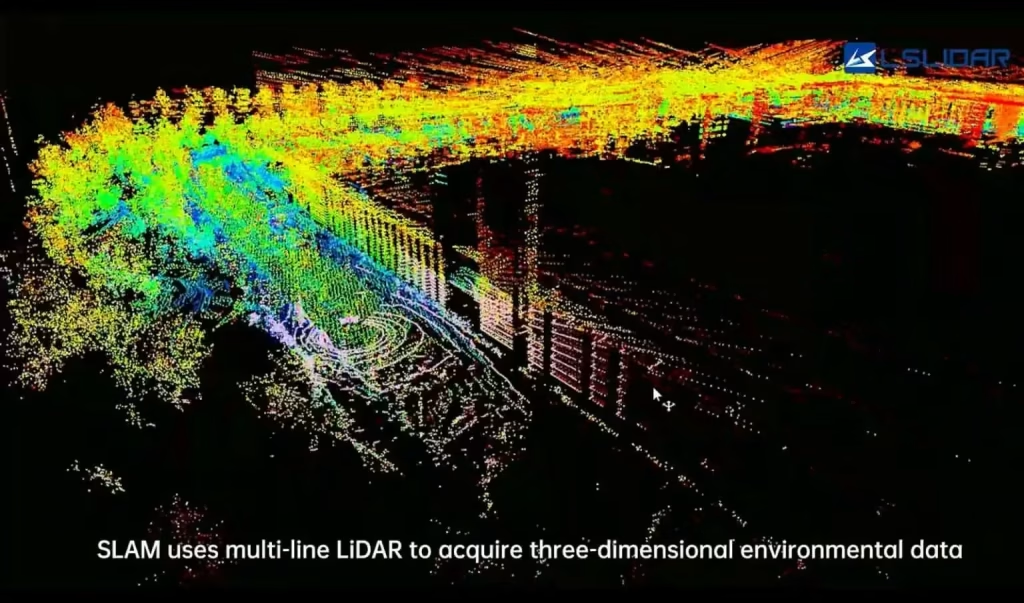
Lidar SLAM (Light Detection and Ranging Simultaneous Localization and Mapping) is a technology that allows a robot or autonomous system to build a map of an unknown environment while simultaneously determining its own position within that map in real time. The technology relies on LiDAR sensors, which emit laser pulses and measure the time it takes for those pulses to reflect back after hitting objects. By analyzing the returned laser signals, a Lidar SLAM system can generate high‑precision 3-dimensional point clouds representing the environment, and use this information to estimate the robot’s position and orientation within the map.
Recommended In-depth Reading from AI Robots Eidos
SLAM (Simultaneous Localization and Mapping) is a broad technical concept that refers to the technology of simultaneously achieving self-localization and environmental map construction in an unknown environment. Laser SLAM is a specific implementation of SLAM technology that utilizes laser radar sensors to gather environmental information. By processing the point cloud data collected by the laser radar, it achieves localization and mapping.
If readers are not very familiar with SLAM, they can first read this article about SLAM (Simultaneous Localization and Mapping).
How LiDAR SLAM Works
To help readers understand the basic principles of Lidar SLAM, this article explains them from a procedural perspective: the mechanism of SLAM (simultaneous localization and mapping), the role of LiDAR sensors, and map generation and robot pose estimation in LiDAR SLAM.
Mechanism of SLAM (Simultaneous Localization and Mapping)
The core idea of SLAM is to allow a robot or autonomous system to build a map of an unknown environment while simultaneously determining its own location within that map. This goal is achieved by fusing data from multiple sensors (e.g., LiDAR, cameras, and inertial measurement units, IMUs) to estimate the robot’s trajectory and the positions of landmarks in the environment. SLAM algorithms typically consist of two main steps: prediction and correction.
The prediction step (also called motion update or odometry update) estimates the robot’s new position based on its previous position and motion information provided by its sensors. The correction step (also called observation update or sensor update) refines the predicted position using measurements of the environment (e.g., distances to landmarks detected by LiDAR). By iteratively performing prediction and correction, the SLAM algorithm continuously updates the robot’s position and the environmental map. The resulting map can be represented in various forms, such as occupancy grids, point clouds, or graphs capturing spatial relationships between landmarks.
Role of LiDAR Sensors in LiDAR SLAM
LiDAR sensors play a critical role in LiDAR SLAM systems by providing high‑precision, high‑resolution environmental data. These sensors emit laser pulses that reflect off objects and return to the sensor, and the system measures the distance to objects by calculating the time‑of‑flight of the pulses. LiDAR can generate dense 3-Dimensional point clouds – sets of points in three‑dimensional space that represent the surfaces of objects in the environment.
These point cloud data can be used to identify and track landmarks in the environment, such as walls, corners, or other salient features. Such landmarks are essential to the SLAM algorithm because they provide information that can be used to refine estimates of the robot’s position and orientation. Furthermore, LiDAR data can also be used to identify and avoid obstacles, making it highly valuable for autonomous navigation and safe operation.
Map Generation and Pose Estimation in LiDAR SLAM
Using LiDAR data to generate a map and estimate the robot’s pose (position and orientation) within that map is the core process of LiDAR SLAM. Maps can be represented in several forms: for example, an occupancy grid map, where each grid cell indicates the probability that the location is occupied by an object; or a point cloud map, where the positions of objects in the environment are presented as a set of points in 3-Dimensional space. To estimate the robot’s pose, the SLAM algorithm uses LiDAR data to identify and track landmarks in the environment.
By comparing observed landmarks with those already stored in the map, the algorithm determines the robot’s position and orientation relative to the map. This process typically involves finding the optimal transformation matrix that aligns the current LiDAR scan with the existing map, using techniques such as Iterative Closest Point (ICP) or other optimization algorithms.
As the robot continues to explore the environment and collect new LiDAR data, the map is continuously updated, and the robot’s pose is progressively refined. This iterative mechanism enables Lidar SLAM systems to achieve high‑precision mapping and real‑time localization in a variety of applications, from autonomous vehicles to mobile robots and indoor mapping.
Types of LiDAR Sensors for LiDAR SLAM
There are many types of LiDAR sensors, each with unique characteristics and advantages. Selecting the appropriate LiDAR sensor for a specific LiDAR SLAM application is important.
–Mechanical Rotary LiDAR: Mechanical rotary LiDAR is one of the most common types in SLAM applications. It consists of a laser emitter and receiver mounted on a rotating platform that scans a wide area by rotating. Such sensors can generate high‑resolution point clouds and have detection ranges of up to 200 meters (depending on the model and configuration).
The Velodyne HDL‑64E is a mechanical rotary LiDAR widely used in autonomous driving and robotics. It features 64 laser scanning beams, a 360° horizontal field of view, a 26.9° vertical field of view, a maximum detection range of 120 meters, and an angular resolution of 0.08°. Its high resolution and wide field of view make it well‑suited for SLAM applications that require detailed environmental data.
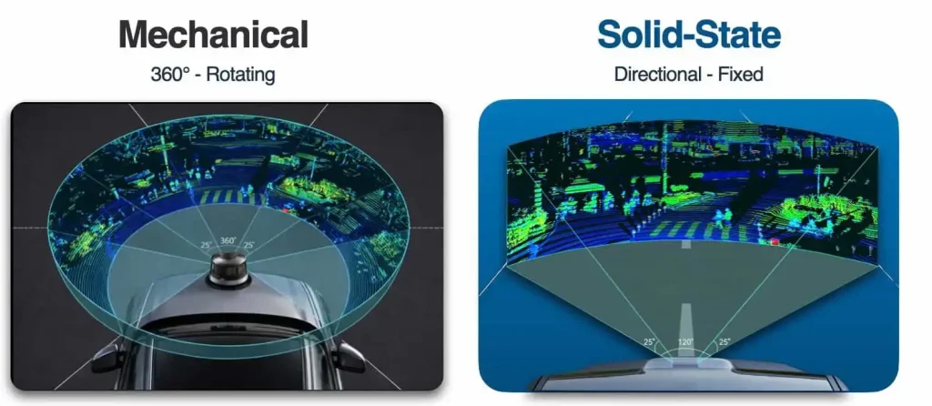
–Solid‑State LiDAR: Solid‑state LiDAR represents a new generation of LiDAR technology that scans the environment without moving mechanical parts. It uses electronic beam‑steering techniques (such as optical phased arrays or MEMS mirrors) to direct laser pulses across the field of view. Compared to mechanical LiDAR, solid‑state LiDAR offers greater durability, lower power consumption, and smaller size and weight. The InnovizOne is a solid‑state LiDAR designed for automotive and robotics applications. It has a maximum detection range of 250 meters, a horizontal field of view of 73°, a vertical field of view of 20°, and an angular resolution of 0.1°, providing high‑precision point cloud data suitable for SLAM scenarios that demand high environmental accuracy.
–Flash LiDAR: Flash LiDAR is another solid‑state technology that illuminates an entire scene with a single wide‑angle laser pulse and captures the reflected light with a 2-dimensional sensor array. This sensor enables single‑shot measurement of the environment, making it particularly suitable for applications that require high‑speed data acquisition, such as aerial mapping or obstacle detection in high‑speed autonomous vehicles. For example, the ASC TigerCub is a flash LiDAR designed for robotics and aerial mapping. It offers a maximum detection range of 150 meters, a horizontal field of view of 90°, a vertical field of view of 20°, and a spatial resolution of 1 cm, providing high‑precision mapping and localization capabilities to SLAM systems.
Key Technical Specifications of LiDAR Sensors in LiDAR SLAM Systems
LiDAR is critical to the performance of LiDAR SLAM. The following are some core technical specifications of LiDAR, which we hope will help readers better understand LiDAR SLAM.
–Detection Range: Detection range refers to the maximum distance at which a LiDAR sensor can detect a target object. It determines the effective coverage of the LiDAR in a given application scenario. Note that the detection range is affected by many factors (target reflectivity, target reflective area, atmospheric conditions). Therefore, when selecting a sensor, one should understand its actual ranging capability under specific conditions.
–Angular Resolution: Angular resolution refers to the angular interval between two adjacent detection points of a LiDAR sensor, and it includes both horizontal and vertical angular resolutions. The smaller the angular interval between adjacent points, the stronger the sensor’s ability to resolve fine details of a target. Angular resolution is related to the scanning speed and precision of the LiDAR. For applications requiring high‑precision measurement, a LiDAR with high angular resolution should be chosen.
–Field of View (FoV): The field of view of a LiDAR determines the spatial extent of the environment that can be covered in a single scan. A wide FoV allows a Lidar SLAM system to map larger areas and detect objects from different angles, which is particularly critical for applications that require comprehensive situational awareness, such as collision avoidance in autonomous driving or mapping large indoor spaces.
–Ranging Accuracy: Ranging accuracy refers to the consistency of distance measurements taken by a LiDAR sensor for an object at the same distance. Higher accuracy means smaller random measurement errors. Ranging accuracy is influenced by many factors, including laser wavelength, target reflectivity, and atmospheric conditions. When selecting a sensor, one should understand its actual ranging accuracy under specific conditions.
–Scan Frequency: Scan frequency refers to the number of scans a LiDAR sensor can complete per second, which determines the sensor’s data update rate. For applications that require real‑time responsiveness, a LiDAR with a high scan frequency should be chosen. Scan frequency is related to the sensor’s scanning mechanism and processing speed. When selecting a sensor, an appropriate frequency should be chosen based on actual needs and the application scenario.
–Power and Power Consumption: The laser emission power of a LiDAR and its power consumption during normal operation. The power determines the sensor’s detection and penetration capabilities, while power consumption affects the device’s endurance and operating costs.
–Scanning Method: The scanning method of a LiDAR can be either mechanical scanning or solid‑state scanning. Mechanical scanning achieves scanning through rotation or oscillation, offering a wide scanning range but a slower speed. Solid‑state scanning uses technologies such as arrays or MEMS (Micro‑Electro‑Mechanical Systems) to achieve fast scanning, providing higher scanning speeds and smaller form factors.
–Laser Wavelength: Laser wavelength determines the penetration and anti‑interference capabilities of a LiDAR. Lasers of different wavelengths respond differently to various materials and environmental conditions. Common laser wavelengths are 905 nm and 1550 nm, each with its own advantages and disadvantages, making them suitable for different application scenarios.
–Point Rate: Point rate refers to the number of laser points a LiDAR emits and receives per second. It determines the density and resolution of the point cloud data. A higher point rate can provide richer environmental information, but also requires greater computational and processing power.
–Number of Beams (Channels): For multi‑beam LiDAR, the number of beams (or channels) is an important parameter. It determines how many parallel lines the LiDAR can scan simultaneously, thereby affecting scanning resolution and efficiency. A larger number of beams provides more detailed environmental information but also increases device complexity and cost.
–Ingress Protection (IP) Rating: The IP rating indicates the LiDAR’s protection against dust and water. Different application scenarios have different requirements for IP ratings. In harsh environmental conditions, a LiDAR with a high IP rating should be chosen to ensure device stability and reliability.
–Safety Class: The safety class is an indicator of a LiDAR’s safety for people and the environment. It takes into account factors such as laser power, wavelength, and divergence angle. When selecting a LiDAR, one should ensure that it meets relevant safety standards and regulatory requirements.
–Output Parameters: Output parameters include the data format and interface type provided by the LiDAR. These parameters need to be compatible with the system that receives and processes the data to ensure smooth data transmission and processing.
–Operational Lifetime: Operational lifetime is an indicator of a LiDAR’s durability and reliability. When selecting a sensor, one should understand its lifetime and maintenance requirements to ensure that it can meet the needs of long‑term stable operation.
LiDAR SLAM Algorithms
LiDAR SLAM algorithms are the foundation for generating high‑precision maps and accurately localizing autonomous devices within those maps. The development of efficient algorithms has greatly advanced the field of LiDAR SLAM. To help readers understand the latest knowledge in Lidar SLAM, this article only introduces some relatively new algorithms. Among them, R3LIVE is the main focus of the introduction.
There will be dedicated articles in the future that provide detailed descriptions of more Lidar SLAM algorithms.
R3LIVE Algorithm:
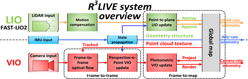
The R3LIVE consists of two subsystems: a Lidar-Inertial Odometry (LIO) and a Visual-Inertial Odometry (VIO). The LIO subsystem (FAST-LIO) utilizes measurement data from the laser radar and inertial sensors to construct the geometric structure of the map (i.e., positions of 3-Dimensional points). The VIO subsystem uses data from visual-inertial sensors to render the texture of the map (i.e., colors of 3-Dimensional points). More specifically, the VIO subsystem effectively integrates visual data by minimizing the photometric error from frames to the map.
Advantages: High accuracy is achieved through tightly coupled data from Lidar, inertial, and visual sensors, combined with an Error State Iterative Kalman Filter (ESIKF) framework, resulting in high-precision state estimation and map reconstruction. Testing on public datasets (such as NCLT) and private datasets shows that its localization accuracy surpasses most similar algorithms, especially maintaining low drift even after long-distance operation.
It also possesses strong robustness, maintaining good localization and mapping performance in degraded scenarios for Lidar (such as long tunnels or single planar walls) and visually weak textured environments (like white walls or low light), effectively alleviating sensor degradation issues by supplementing the Lidar weaknesses with visual information.
Disadvantages: Although it can run on standard CPUs, it still requires certain computational resources when processing high-resolution images or large-scale scenes, with higher computing power demands for embedded platforms. The original version of R3LIVE did not include a strong loop detection mechanism; thus, long-term operation may incur cumulative errors. While R3LIVE++ has improved robustness through algorithm enhancements, its loop closure detection capability still has room for improvement compared to dedicated loop detection algorithms.
LIO-SAM Algorithm:
The LIO-SAM algorithm reconstructs the entire system into a factor graph framework, unifying laser odometry, IMU pre-integration, loop closure detection, and GPS observations into a graph optimization problem, while employing a sliding window to control the computational scale. This represents a structural leap from “filtering” to “graph optimization.”
Advantages: The factor graph framework provides global consistency, supports multi-sensor fusion (IMU, GPS), and has mature loop closure detection.
Disadvantages: The computational cost is relatively high, with significant requirements for the computational platform; it does not incorporate visual data, and pure laser data still carries risks in degraded environments.
FAST-LIO Algorithm:
The FAST-LIO algorithm series does not rely on graph optimization. FAST-LIO uses feature points, while FAST-LIO2 re-registers using raw point clouds and introduces the ikd-Tree; Faster-LIO replaces the ikd-Tree with iVox (incremental voxel hashing), continuously improving real-time performance.
Advantages: Excellent real-time performance, with FAST-LIO2 achieving over 100 Hz and Faster-LIO reaching 1-2 kHz for solid-state LiDAR; the IEKF architecture is highly adaptable to high-speed motion (1000°/s angular velocity); direct registration of raw point clouds offers good versatility.
Disadvantages: Lacks loop closure detection, resulting in cumulative drift over long-term operation; accuracy is slightly lower than LIO-SAM-type graph optimization solutions.
Lidar SLAM Selection Based on Actual Needs (For Reference Only)
To further assist readers in understanding Lidar SLAM, two examples are provided for reference purposes.
Outdoor Scenes
—Sensor Choices: Priority should be given to high-resolution, long-range Lidar sensors (such as 64-line or solid-state Lidar) or a combination of stereo cameras and IMU. Lidar can handle complex terrains and long-distance mapping, while the stereo camera + IMU combination can provide supplementary positioning in areas with weak GPS signals (such as urban canyons).
—Algorithm Choices: If real-time performance is required, the FAST-LIO series can be selected, as it is adapted for high-speed motion. For high precision and global consistency, LIO-SAM or VINS-Fusion can be chosen, which integrates Lidar, IMU, and GPS data to achieve centimeter-level positioning.
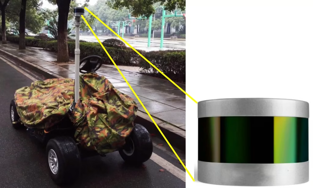
—Trade-offs: The outdoor environment experiences significant lighting changes and sparse features; thus, the sensor’s resistance to interference (such as Lidar’s resistance to sunlight) should be considered. Increasing the loop closure detection frequency is also necessary to reduce cumulative errors.
High-Speed Motion Scenarios
—Sensor Choices: A Lidar sensor with a high update frequency (such as flash Lidar) or an IMU should be selected to ensure the ability to capture environmental changes during fast motion.
—Algorithm Choices: The FAST-LIO algorithm should be prioritized for its high computational efficiency, allowing real-time processing of high-speed motion data. However, for higher precision, it can be combined with graph optimization algorithms, keeping computational complexity in check.
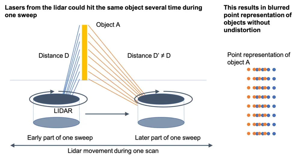
—Trade-offs: High-speed motion can lead to blurriness or loss of sensor data, so it is essential to increase data preprocessing (such as motion compensation) and implement anomaly detection mechanisms to ensure positioning stability.
Applications of LiDAR SLAM
With technological advances and increasing adoption, Lidar SLAM has been widely used across many industries.
–Industrial Sector: In scenarios such as warehouse logistics and manufacturing workshops, Lidar SLAM enables Autonomous Mobile Robots (AMRs) to perceive the environment in real time, build maps, and accurately localize themselves, thereby achieving autonomous path planning, obstacle avoidance, and goods transportation. For example, in narrow aisles or environments with many dynamic obstacles, the system can flexibly navigate and efficiently handle material transport tasks, improving logistics efficiency.
Recommended In-depth Reading from AI Robots Eidos
LIDAR SLAM is one of the core technologies enabling Autonomous Mobile Robots (AMRs) to achieve autonomous navigation. AMRs utilize LiDAR sensors to gather real-time data about their surrounding environment through LIDAR SLAM algorithms, constructing environmental maps while simultaneously determining their own location within these maps. This allows for autonomous localization, path planning, and obstacle avoidance capabilities. The widespread application of AMRs has also driven the continuous development and optimization of LIDAR SLAM technology.
For readers interested in understanding the relationship between these two concepts, please refer to this article on Autonomous Mobile Robots.
–Transportation Sector: Lidar SLAM is a core component of autonomous driving technology. On‑board LiDAR sensors scan the surrounding environment in real time, generating high‑precision 3-Dimensional point cloud maps, identifying road boundaries, lane markings, traffic signs, obstacles, etc., and providing an environmental model for the autonomous driving system.
By combining LiDAR data with vehicle motion information, the system determines the vehicle’s precise position (with centimeter‑level error) within the map in real time. Based on the constructed map and real‑time perception information, it plans driving routes and dynamically adjusts paths to avoid obstacles, ensuring driving safety.
–Agricultural Sector: Drones equipped with Lidar SLAM can build environmental maps in real time, enabling autonomous navigation and precise execution of tasks such as seeding, fertilizing, spraying, and harvesting, reducing manual intervention and improving operational efficiency and accuracy. Lidar SLAM can also capture 3-Dimensional structural information of crop canopies (e.g., tree height, crown width, leaf area index). Combined with time‑series data, it can monitor crop growth status and assess growth trends.
Challenges and Solutions in LiDAR SLAM
Sensor Limitations
–Challenge: LiDAR sensors have limited detection ranges beyond which reliable data cannot be obtained. Resolution and accuracy are affected by environmental factors (e.g., varying point cloud density, feature extraction difficulties in low‑texture scenes such as long corridors or tunnels). A limited field of view may cause environmental information to be missed.
–Solutions: Choose LiDAR sensors with high resolution and a wide field of view. Use multi‑sensor fusion (e.g., with IMUs and visual sensors) to supplement information and improve localization accuracy. Adopt adaptive sampling algorithms that dynamically adjust point cloud sampling density based on the scene.
High Computational Complexity
–Challenge: Lidar SLAM algorithms, especially when processing large‑scale environments or high‑resolution data, impose high computational demands, creating real‑time performance pressures and requiring powerful hardware.
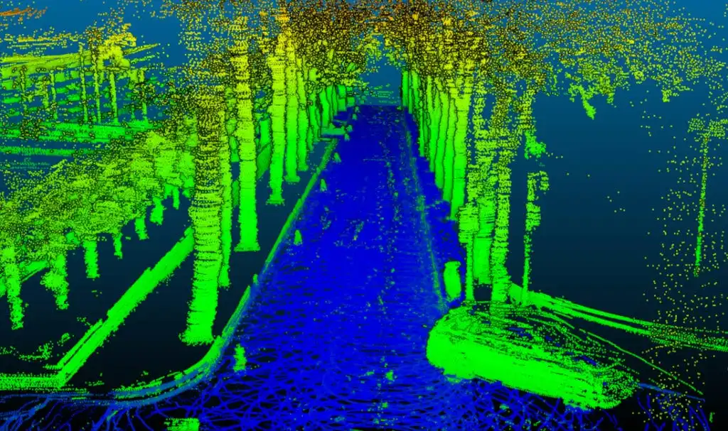
–Solutions: Use distributed computing architectures to split computational tasks across multiple parallel nodes. Optimize algorithms by employing sparse representations, hierarchical mapping, and other methods to reduce computational load. Leverage hardware acceleration (e.g., GPUs, FPGAs) to improve computational efficiency.
Difficulty Handling Dynamic Environments
–Challenge: Most SLAM algorithms assume a static environment, but real‑world scenes often contain dynamic objects such as pedestrians and vehicles. Distinguishing dynamic from static objects is difficult, leading to inaccurate map updates.
–Solutions: Use semantic segmentation to identify dynamic objects and remove them from the point cloud, constructing a static map. Introduce dynamic object tracking algorithms that update the positions of dynamic objects in real time to prevent them from interfering with localization.
Loop Closure and Global Consistency
–Challenge: Achieving global consistency in large‑scale or long‑duration missions is a major challenge. Loop closure (i.e., recognizing that the robot has returned to a previously visited location) is difficult due to the high dimensionality of LiDAR data and the existence of “perceptual aliasing” (different places that look similar), leading to globally inconsistent maps.
–Solutions: Adopt multi‑feature fusion methods for loop closure detection, combining geometric features, semantic features, etc., to improve detection accuracy. Introduce global optimization algorithms (e.g., pose graph optimization) to correct drift and ensure global map consistency.
Future Directions of LiDAR SLAM
–Integration with Deep Learning: In LiDAR SLAM, because point cloud data lacks texture information and contains relatively little information, its integration with deep learning is less mature than in visual SLAM. Deep learning is mainly applied to point cloud feature extraction and registration, and point cloud semantic segmentation. PointNet is an excellent point cloud classification and segmentation model; the global features it extracts perform well for classification tasks, but its local feature extraction capability is limited. PointNet++ proposes a multi‑level feature extraction structure that improves local feature extraction, compensating for PointNet’s shortcomings.
–Multi‑Sensor Fusion: LiDAR can provide precise spatial coordinates but lacks texture information and fails in rainy or foggy environments. A single sensor has limited applicability and cannot handle such complex conditions well. Multi‑sensor fusion is key to solving the robustness problem of SLAM algorithms in complex environments. Millimeter‑wave radar is unaffected by rain, snow, or dust and has better penetration, so it can be fused with Lidar SLAM to compensate for LiDAR’s shortcomings. The IMU does not depend on the external environment and can perform high‑frequency measurements, making it an indispensable part of multi‑sensor fusion.
Insight from AI Robots Eidos about LiDAR SLAM
—Based on implicit neural representations (NeRFs/Neural Fields) for Lidar SLAM: Traditional LiDAR SLAM relies on explicit point clouds, grids, or feature maps, which suffer from large storage requirements and poor performance in sparse or occluded areas. In the future, neural radiance fields (NeRFs) or more general neural implicit representations can be introduced into LiDAR SLAM to directly encode the environment’s continuous geometry and reflectance fields using neural networks.
—Online semantic field updates for dynamic environments: To develop online semantic field SLAM, dynamic objects can be modeled as “entities” with independent motion models, optimized alongside a static background map. By combining semantic segmentation of Lidar point clouds (e.g., RangeNet++) with multi-object tracking, we can maintain the pose trajectories for each dynamic object while simultaneously updating their influence areas in the environment in real-time. The map is no longer a singular static occupancy grid but a layered spatiotemporal field.
—Event-driven LiDAR SLAM and asynchronous perception architecture: Traditional LiDAR SLAM processes complete scan frames at a fixed frequency, resulting in a high computational load and fixed response latency. Inspired by the asynchronous and low-latency concepts of event cameras, event-driven Lidar SLAM can be developed: instead of processing all points in each frame, it only processes laser points that exhibit significant changes in space or time (such as newly emerging edges or the leading edges of moving objects).
Image Credits: Lslidar & Kudan & Thinkautonomous & Livoxtech & Mdpi & Sama